This thread has been locked.

If you have a related question, please click the "Ask a related question" button in the top right corner. The newly created question will be automatically linked to this question.

INA220: Bus Voltage Full Scale Range Setting

Part Number: INA220
Other Parts Discussed in Thread: INA239, INA238, INA228, INA229

Hi Team,

I have questions on the bus voltage calculation in INA220. 

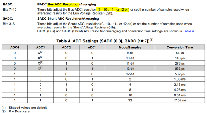
1. Bus voltage can be sampled in 9-, 10-, 11-, or 12-bit by BADC bit in the configuration register. 

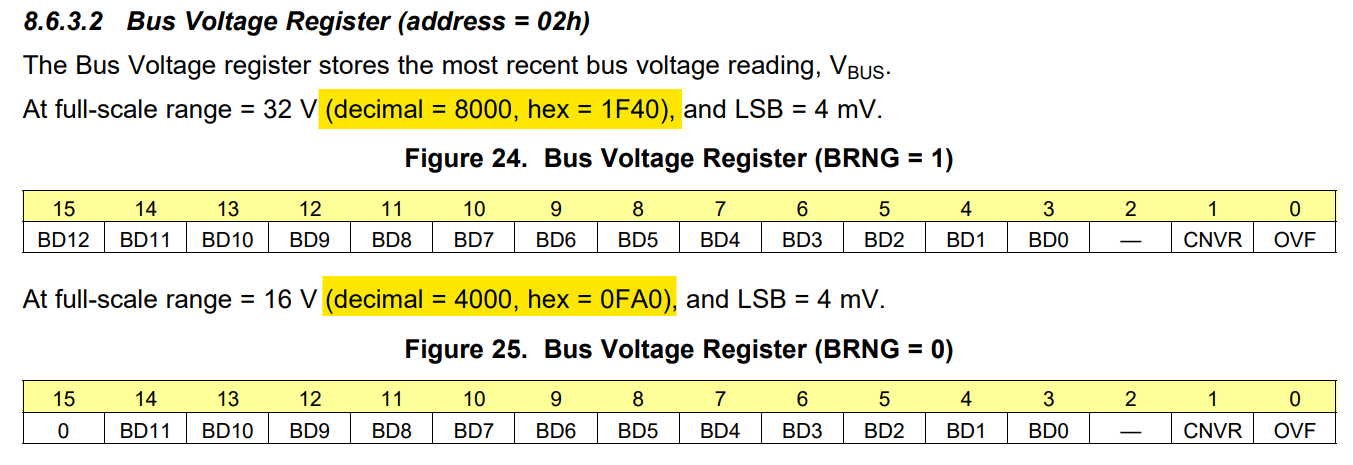
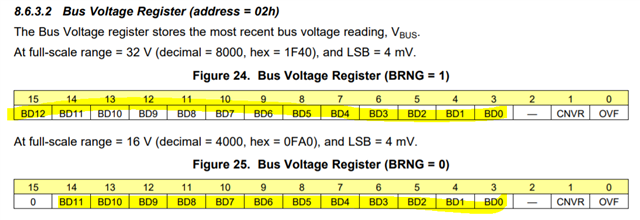
But it looks bus voltage is basically 13bit (02h[15:3]) when 32-V FSR, and 12 bit (02h[14:3]) when 16-V FSR. 

Q1. With 32-V FSR, how the 13 bit of register 02h works with 12-bit resolution ADC?

Q2. With 16-V FSR, would the bus voltage value be right-aligned or left-aligned, if ADC resolution setting is 9 bit?

2. Could you help me to understand the basic concept of FSRs? There are two FSRs, 32V and 16V. What I understand so far is : 

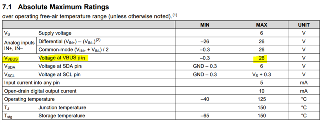
If I set 32V FSR, 26V of VBUS would be corresponding to 32V. So 26V can be divided into 8000 steps. 

VBUS = 26V ---- 02h [15:3] = 1F40 h = 1 1111 0100 0000 b (32/4mV * 26/26 = 8000 --> 1F40 h)

VBUS = 13V ---- 02h [15:3] = 0FA0 h = 0 1111 1010 0000 b (32/4mV * 13/26= 4000 --> 0FA0 h)

If I set 16V FSR, 26V of VBUS would be corresponding to 16V. So 26V can be divided into 4000 steps.

VBUS = 26V ---- 02h [14:3] = FA0 h = 1111 1010 0000 b  (16/4mV * 26/26 = 4000 --> FA0 h)

VBUS = 13V ---- 02h [14:3] = 7D0 h = 0111 1101 0000 b (16/4mV * 13/26= 2000 --> 7D0 h)

But I realize something wrong on my understanding. Because my calculation is different from 9.2.2 in the datasheet. 

Q3. According to 9.2.2 in the datasheet, 11.98V of VBUS would be stored as 02h [14:3] = BB3h with 16-V FSR. What 02h[15:3] would be if I set 32-V FSR and apply 11.98V on VBUS? It would help for me to understand the basic concept of Bus voltage FSR.

Thanks.

  • Hello Ella,

    Thank you for using the TI forum. Here are my responses to your questions:

    Q1: The reason the 12 bit ADC value goes into a 13 bit register is so that the result value can utilize higher resolution when averaging samples.  

    Q2: For measurement convenience, the lsb of the bus voltage register is always 4mV, so the same measurement value will always show the same in the bus voltage register regardless of the ADC settings.  The trade-off of changing the ADC setting is less accuracy/resolution for a faster result.  If you do 16-V FSR, with 9-bit ADC, the result is not right or left aligned into the 12 available bits, but still reads out with an LSB of 4mV. 

    Q3: Changing the FSR between 16 and 32 affects the measurement range of the ADC, but does not change the LSB of the bus voltage result register. So, 11.98V on VBUS will read out as 0xBB3 regardless of the FSR or averaging settings used. 

  • Hi Mitch,

    Thank you for your response.

    When it comes to your response on Q3, I don't think I fully understand how it works. If the VBUS register value would be same as 11.98V and the LSB would be same as 4mV, why INA220 has two options of FSR? 

    Changing the FSR between 16 and 32 affects the measurement range of the ADC

    Could you kindly help me to understand your comment above?

  • Hello Ella,

    I understand that this can be a little confusing.  I believe the confusion comes from the internal ADC bit resolution vs the register result bit resolution.  What I meant by my comment above is that the FSR changes the internal ADC range, but does not change the register result output format.  So, when you change ranges on the ADC from 32V to 16V, you will get higher resolution between 0V and 16V than you would at 32V range, but the value is converted to a uniform output format for convenience. 

    It is also important to note that when using lower bits resolution, every bit code may not be available in the register result output (as this register is large on purpose to accommodate all modes).  For example, if you are using 16V range with only 9 bit ADC, then the ADC resolution is 16/512 = 31.25 mV.  With this setup, the result register would still show in 4mV LSBs, so the output will not use every code, as you couldn't measure down to 4mV.

    So, although the VBUS result register for 11.98V will be the same register output code of 0xBB3 at both 16V and 32V FSR, you will have more precision and noise free accuracy in the 16V FSR than you would at 32V FSR. Plus that code may not be measurable based on the configured ADC and averaging settings. 

  • Hi Mitch,

    Thank you for your kind reply.

    I'm trying to understand it. Could you kindly check if my understanding below are correct?

    1. 16V FSR and 12-bit ADC --> LSB = 16/(2^12-1) = 3.97mV

    32V FSR and 12-bit ACD --> LSB 32/(2^12-1) = 7.81mV ; this is why you mentioned below.

    ou will get higher resolution between 0V and 16V than you would at 32V range

    2. 32V FSR and 9-bit ADC --> LSB = 32/(2^9-1) = 62.6mV

    If I apply 12V on VBUS pin, what value would be stored in Bus voltage register [15:3]? I believe bit [15] would be 0 and bit [14:3] would be BB0h. (The reason is below.) BB0h is equivalent to 2992 in decimal and this value of 2992 multiplied by the 4-mV LSB results in a value of 11.968 V. This is inaccurate result due to the low ADC resolution (9-bit), because the actual VBUS voltage is 12V, not 11.968V.

    - 12V/64mV = 187.5 which will be 187 (0BBh) during the quantization

    - 0BBh becomes BB0h to meet 4mV LSB format

    3. The max bus voltage that the internal ADC can read is only upto 16.38V (when 0x02 = 7FF1h --> 0FFFh = 4095d) if I set 16V FSR. And the max bus voltage is upto 32.764V (when 0x02 = FFF1h --> 1FFFh = 8191d) if I set 32V FSR, but INA220's bus voltage limitation would be <26V as specified in 7.1 in the datasheet.

    Thank you for your help again.

  • Hello Ella,

    Below are my responses to your questions.  As a side note, I had made a small math error in my earlier message, but have corrected it now (512 instead of 511....).  Consequently, you used the same process as me in your math, so those will be slightly off (you don't need the "-1").

    1. Yes, this is why you will get higher resolution at 16V range. (note that with the math error I mentioned, these will be 3.90625mV and 7.8125mV respectively)

    2. (Updated math correction puts the calculation to 62.5mV).  With this math correction, I'll rerun the numbers above: 

    With a 32V FSR and 9 bit ADC, with 12V, the ADC LSB would be 7.8125mV, which would be and ADC code of 1536 (0x600). This then gets converted to the output register format in hex code 0xBB8, which is 3000 decimal.  Then multiplying by the LSB of 4mV, we get 3000 * 0.004 = 12V.

    So, in this case, 12V measurement does work fine, sorry for confusing you with my math error earlier.

    3. I do not see a question here, but I will try to clarify.  First, the max voltages are actually 32V and 16V, not 16.38 and 32.764.  This is because  the LSB of 4mV is a chosen value, not based off off the max possible in the output register.  Consequently, the value 0x0FFF and 0x1FFF you mentioned above are not actually measurable. The max value at full scale rage is shown in the datasheet: 

    That being said, you are correct, although 32V is used for the ADC FSR, 26V is still the max value allowed on the VBUS pin.

    Hope that helped answer your questions.

    On another note, if you are looking for higher voltage or more accuracy, you can always look into our newer line of digital INA's, the INA228 (20 bit I2C) and INA229 (20 bit SPI).  If those are too expensive we have 16 bit versions as well, the INA238 (16 bit I2C) and INA239 (16 bit SPI).

  • Hello Mitch,

    Thank you for your kind response again. I understood the your comments on #1 and #3 but I still have some unclear areas for me..

    (you don't need the "-1").

    To my knowledge, substituting 1 is a normal process when calculating LSB. I refer to app. note (https://www.ti.com/lit/an/slaa013/slaa013.pdf). Can I just calculate with (2^n), not with (2^n-1)?

    With a 32V FSR and 9 bit ADC, with 12V, the ADC LSB would be 7.8125mV,

    I believe LSB should be 62.5mV because it's 9-bit ADC. But you mentioned 7.8125mV. Could you correct me if any misunderstanding?

    (32V FSR and 9-bit ADC --> LSB = 32/(2^9) = 62.5mV)

    (32V FSR and 12-bit ADC --> LSB = 32/(2^12) = 62.5mV)

    ADC code of 1536 (0x600). This then gets converted to the output register format in hex code 0xBB8, which is 3000 decimal.

    Could you kindly give me more information on how 1536 (0x600) is converted to 3000(0xBB8)?

  • Hey Ella,

    Sorry for the confusion.... looking more into the "-1" part of the equation, it turns out that the equation both with and without the "-1" have been used historically. Doing the math without the "-1" is an easy approximation and usually gives a nicer LSB, while adding the "-1" is a more technically accurate/correct equation.

    Yes, I accidentally calculated for 12 bit, not 9 bit.....  so the lsb would be 62.5mV, (or rather 62.6223 when using the "-1"). But in general, you will have less resolution with 9 bit ADC, so that can cause error.

    I do not have access to how the exact conversion is done, but in general I believe it converts the data taking into account the new LSB of 4mV, not just by converting the number to the new new bit size directly. 

  • Mitch,

    Thank you for clarification. Lastly could you please check how the conversion into 4mV LSB format is done? I believe there should be any guide document or something regarding how INA220 operates with ADC and registers. Otherwise, testing the EVM and comparing the results is the only way to check its operation?

  • Hello Ella,

    We actually don't give out that level of detail for our devices, but the accuracy will be what is specified in the datasheet. If you want more info on how to look at accuracy and error sources, feel free to look over our TI Precision Labs video's, found here: https://training.ti.com/ti-precision-labs-current-sense-amplifiers, (Section 3 is all about error sources).