This thread has been locked.

If you have a related question, please click the "Ask a related question" button in the top right corner. The newly created question will be automatically linked to this question.

OPA365: OPA365 Stability Analysis with TINA-TI

Part Number: OPA365
Other Parts Discussed in Thread: TINA-TI,

Hello

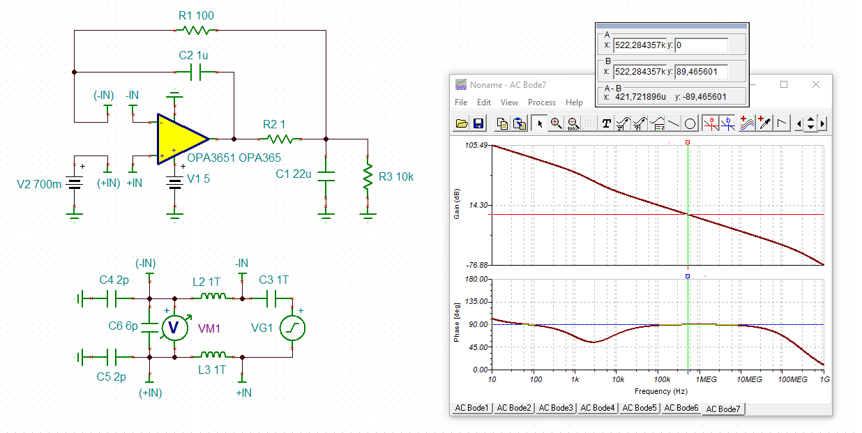
I have designed simple 0.7V reference voltage follower buffer circuits with TINA-TI

I choose OPA365 because it have IN/OUT Rail to Rail and high Current supply with High Bandwidth, good offset voltage.

The R1 1ohm Resister is placed for driving high capacitive load.

However I'm confusing the stability simulation of this kind of circuit. Would you help me?

1.  Is it correct to check the "Vout"(Green),which is a Direct Output of OPAMP.  instead of actual output "Vout2"(Red) to analyze the stability?

I think it right to refer "Vout" pin for make Loop Gain point for negative Input.

"Vout"have about 90 degree phase margin. So It is very stable 

However I will use the "Vout2" output for actual application. Is it ok?

2. The C1 is necessary?

I think it is for in loop compensation, but there is no changes even i get rid of the C1 at AC simulation.

I don't know why. Is it ok to get rid of this capacitor?

  • Hi Sangbeom,

    your circuit is stable:

    sangbeom_opa365.TSC

    Avoid a sudden turn-off of supply voltage, though. In this case the 22µF cap will discharge into the OPAmp output and a high current spike will flow through the internal ESD protection diodes. With 0.7V there isn't probably enough energy for a damage. But I would recommend a ramp-down time of supply voltage of >1msec, which is ten times 5 x R1 x C3 (in your schematic).

    Kai

  • Hello Sangbeom and Kai,

      Thank you Kai for the simulation, and really good point on the turn-off supply voltage. 

      Following up on the question with the feedback capacitor. Removing this feedback capacitor will make this circuit unstable:


     The zero in the phase of the loop gain (pole in the noise gain) is necessary to "cancel" out the pole created due to the capacitive load, and regain stability for this circuit.

     If load resistance is fixed,  another way to compensate for this would be to use out of loop compensation rather than in loop compensation:


      Also, yes you can use "Vout2" as output for actual application. 

      We have a video series explaining simulating amplifier stability, which I will link here.

    Thank you,

    Sima

  • Thanks for your kind stability check. I have completely misplaced the voltmeter. I need to study more. Have a nice day!