This thread has been locked.

If you have a related question, please click the "Ask a related question" button in the top right corner. The newly created question will be automatically linked to this question.

OPA690: Small signal generation, SNR, THD performance with a high load

Part Number: OPA690
Other Parts Discussed in Thread: OPA656, OPA820, TINA-TI, OPA810

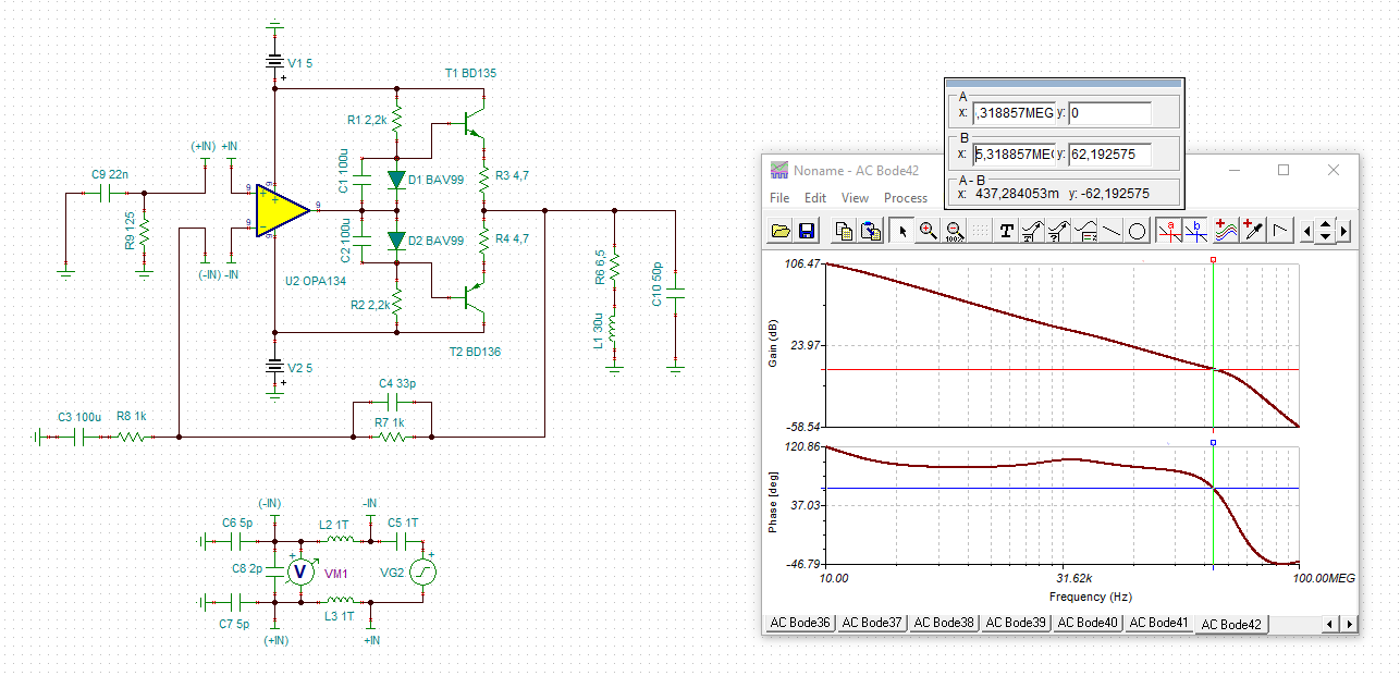
I had to replace an OPA in an existing design. Because of output current drive requirements I selected the OPA690. In my application I need to drive a speaker which has a R_DC of 6.5 OHM and a inductance of 30 uH. Due the signal quality/resolution of the signal generator I need to attenuate the signal of the generator. The AC signal at the OPA input ranges from 1 mVpeak to 400 mVpeak, load currents are in the range of ~170 uA to 61 mA. The signal frequencies are from 20 Hz up to 20 kHz. I'm only interested in the AC performance, some DC offset or drift not really matters. The circuit was working fine for the prototype module. For the productive boards I see big differences in the THD performance, I have 10 dB difference between the boards, some working perfect others are not. All my simulations (step response, AC characteristic, THD, SNR, DC) are okay. For the open loop simulation I get some phase results which I don't understand. I have seen that this is because of the 30 uH inductance. If I only use the 6.5 OHM the phase looks as usual for a noninverted OPA setup. I have the following questions:

1. can I operate the OPA690 in general with the given load and the small input signals, specially regarding SNR and THD
2. would it be better to use a inverted OPA configuration
3. would it be better, due the complex load, to use a serial resistor at the output of the OPA
4. can the OPA operated in the inverted configuration with gains < 1, e.g. 0.1
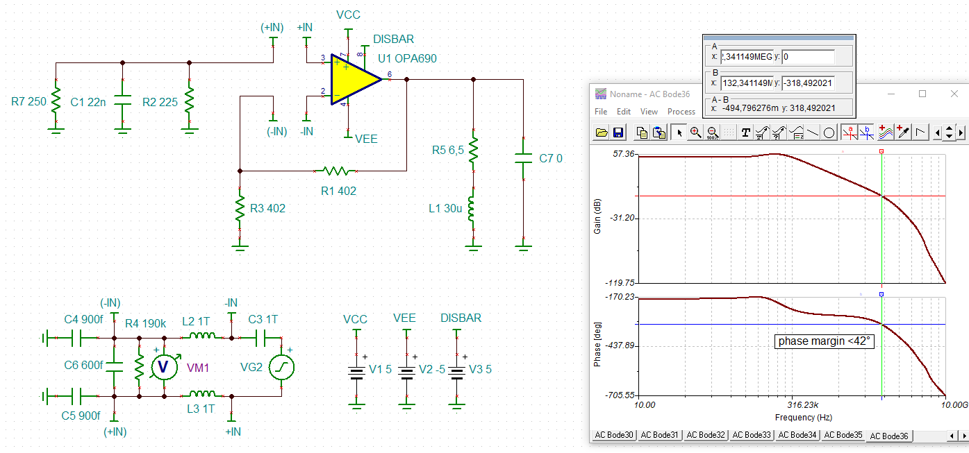
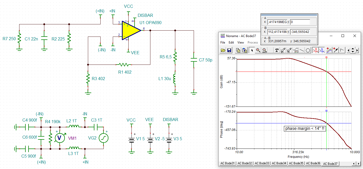
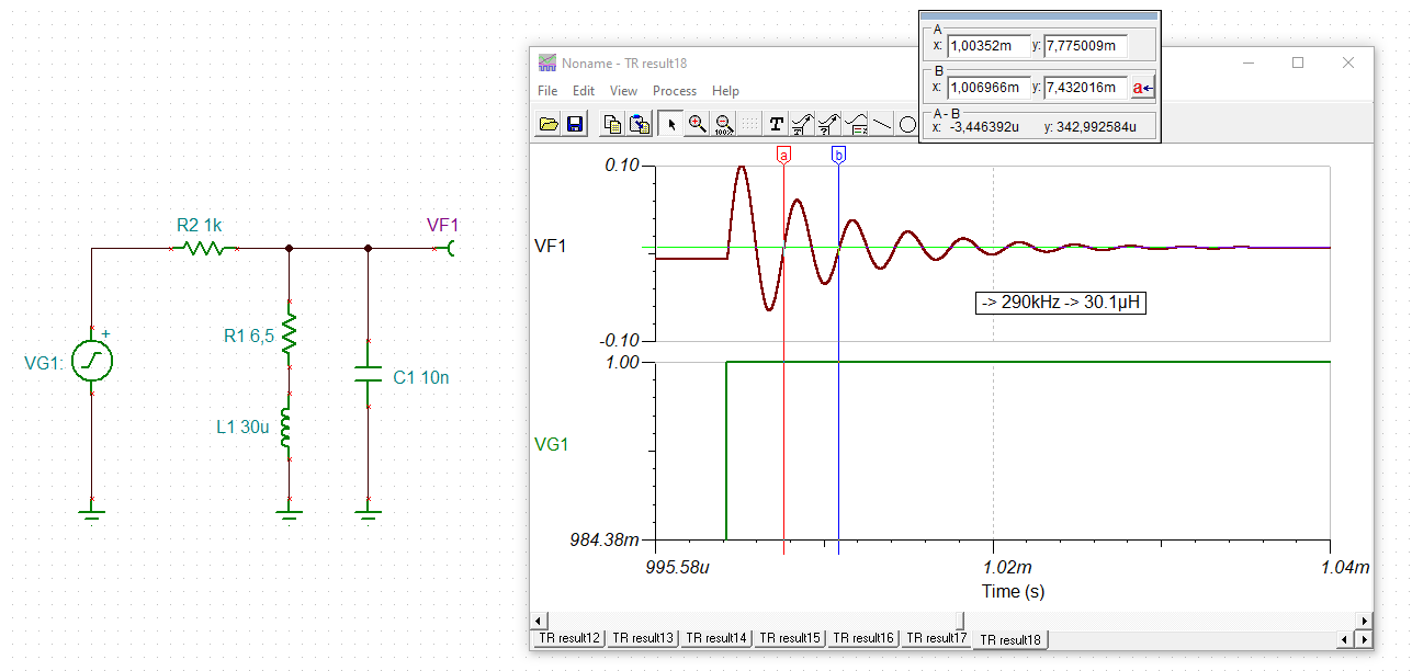
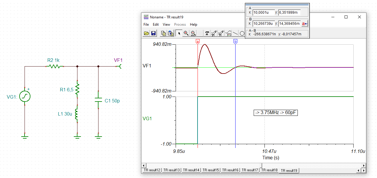
5. any suggestions how to get a correct phase simulation for the open loop simulation with the 30 uH inductance
6. is there any other OPA which could fit better, I searched the TI amplifiers but the problem is the required output current and I need a +/-5V supply. maybe the OPA656

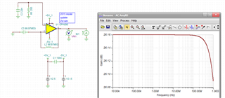
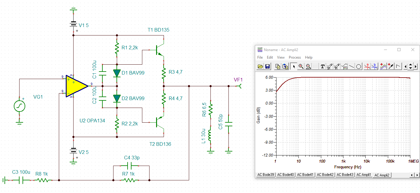
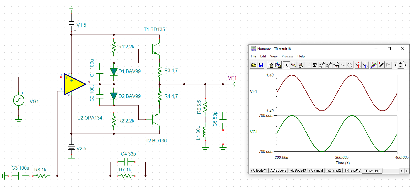
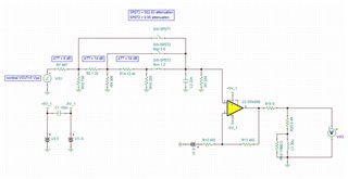
I attached my Tina simulation schematic which I use for the AC,DC,... simulations.

Thank you in advanced, best regards

Jan

  • Morning Jan, 

    The OPA690 was a high slew rate input stage VFA we did to emulate CFA full power bandwidth. Very wideband, but relatively high input voltage noise with higher 1/f corners. You might look at the lower noise, but high output current OPA820. 

  • Hello Jan,

       Thank you for including all this information. Just to clarify, are you seeing 10dB difference in THD between different boards or between the boards and the Tina-TI simulation? Unfortunately, our simulation models are not usually modeled for distortion/THD. To view notes on how the device is modeled, right click on the amplifier symbol and select enter macro:


    1. What are your SNR/THD requirements?

    2. Yes, inverting configuration would increase THD as shown in figures 11 and 12 in the OPA690 datasheet. Also, this would decrease output voltage for the same input voltage range as you have specified. This would consequently increase distortion specs as shown in Figure 10 in the device datasheet. 

    3. Increasing load here would also increase THD, if your application can handle further attenuation at the output of the amplifier

    4. Since this is a unity gain stable amplifier, the OPA690 can be operated in the inverted configuration with gains < 1. For this configuration, be careful with high feedback resistor values. 

    5. Would you be able to share the Tina-TI .tsc file?

    6. Michael suggested a good part alternative. Here are more choices that you can filter down even further using the left column. OPA810 is another product that could work for you.

    Thank you,

    Sima 

  • Hi Jan,

    the phase margin doesn't look very good. 42° is a bit too low:

    And when considering some winding capacitance of your speaker or cabling capacitance, the phase margin fully erodes and your circuit becomes instable:

    jan_opa690.TSC

    Also keep in mind, that the OPA690 sees a 6R5 short-circuit at low frequencies at its output.

    Kai

  • Hello Michael,

    thank you for the fast feedback, I will have a look on the OPA820.

    Best regards

    Jan

  • Hello Sima,

    thank you for the feedback. For the Tina simulation the results are close to the measurement results I achieved with my evaluation board. Based on the evaluation results I went for the final board. For different boards I see the difference in the THD performance. For the THD I need -65 dB for a signal of 1.5 mVpeak and a frequency of 1 kHz. For SNR is around 50 dB for the same signal. I have boards were I achieve these results but for other not, there e.g. THD is -55 dB and SNR is 43 dB. Yesterday I did a ramp check, for the boards with less performance I see a ripple in the output signal not matter what the input level is, ramp signal was from 0 mV...5 mV, for the good boards I get a perfect linear ramp. Therefore the OPA690 can do the job in general. May I have some manufacturing issue with may boards (48 layers and using uVia's). I also plan to replace the OPA690 on the least performing board with an other OPA, like the suggested OPA810 or OPA820.

    Please find the TSC file attached.

    Best regards

    Jan

    TST_OPA690_speaker_driver_TI_TT4.TSC

  • Hi Kai,

    thank you for the feedback, simulation and sharing the TSC file. Yes, phase is not good, optimistic speaking. Your simulation proves what I have also seen but I wasn't sure if I did it correct because of the phase starting at -170 degree. 

    Best regards

    Jan

  • Morning Jan, I was looking at your TINA file, are you sure you don't have some parallel capacitance as part of the load? Surely there is something, even 10pF? That would normally be more harmful to phase margin than the load I see now. 

  • I am actually not seeing much of a phase margin issue with that load - basically open at  xover frequency of 114Mhz, About 42deg phase margin which is fine, 

    However, if you add even a little bit of load C (like trace or wiring cap) that changes dramatically, took more than I expected, but here is 100pF added load - down to 5deg phase margin, 

  • Of course these sort of load dependent phase margin sims are very sensitive to the modelled terms - here, the open loop output Z appears to be just a 20ohm R, sure - I know it actually goes inductive over frequency, so the model is a bit inadequate. And yes, Figure 23 in the data sheet shows a closed loop inductive output Z - that is normal as the loop gain rolls off - but, the internal output stage has its own inductive characteristic open loop wise that is not apparently modelled in this 2015 model - there should be an original model somewhere from the 2001 release date, not in the TINA V11 library - might be interesting to find and check for this. 

  • Hi Jan,

    I would give these scheme a try:

    jan_opa134.TSC

    jan_opa134_1.TSC

    Kai

  • Hello Michael,

    thank you for all the explanations and the simulation. For the simulation I not checked the behavior with a capacitive load. In general, no matter what, I every time go for a prototype.  It was a little bit unfortunate the the prototype was working, hope next time it will be the opposite way ;-).

    I think I know what to do and to check - reduce the capacitive loads in the layout seen by the OPA, verify an other amplifier, optimize the signal chain. Based on the layout, trace capacity a.s.o., I will re-simulate the setup. I will also check the OPA810/OPA820 in my existing board to see if this setup would be more robust.

    Best regards

    Jan

  • Hi Kai,

    thank you for the schematic. I will have a look, may I can do a prototype, to see the space constrains.

    Best regards

    Jan

  • Hello Jan,

      Thank you for the Tina-Ti file and the additional information! Kai and Michael have already given really good suggestions.

      Since there is a difference between boards, like you said, this could be a board manufacturing issue. Looks like you already suggested testing the amplifier from the "good THD board" onto the "bad THD board" and see if that follows the THD/SNR issue. Let us know how that goes. I believe this might be a stability issue which is probably putting the amplifier to unstable behavior depending on board parasitic which Michael and Kai have pointed out. Reducing output capacitance or increasing the isolation resistance which looks like you already are planning to do should help with phase margin. Do keep us updated if there is any improvement. 

    Thank you,

    Sima 

  • Hello Sima,

    thank you for your reply. Yes, it seems that there is a stability issue with the OPA. I have a meeting today with the CAD engineer, wanna check the board parasitic to get some idea for the simulation. I will keep you guys updated.

    Best regards

    Jan

  • Good idea Jan, I would also expect your speaker load to have a non-zero parrallel C. 

  • Hi Michael,

    yes, unfortunately there is no number given in the speaker specification, so need to measure.

    Have a good day, best regards

    Jan

  • Hi Jan,

    you can rather easily estimate the winding capacitance of 30µH inductance by the help of a square wave generator and the scope. The methode is not very precise but simple and you don't need a HF sine generator.

    Firstly, I would verify the inductance by paralleling a precise 10nF (NP0) capacitance. The excitation signal is 1kHz:

    Then, with a 100kHz square wave excitation signal you get this:

    jan_opa690_1.TSC

    The inductance and capacitance is then calculated by the help of Thomson formula. (Don't forget the scope probe capacitance.)

    A more precise method would put the inductance (and external C) in the feedback loop of an OPAmp wired as inverting amplifier with a 2...10k input resistance. Connect a sine generator to the input of inverting amplifier and find the frequency where the output amplitude goes maximum. This is the resonance frequency of LC element. By comparing with a TINA-TI simulation (to take into account the influence of R1) or by applying the Thomson formula, L and C can be found out.

    Kai