This thread has been locked.

If you have a related question, please click the "Ask a related question" button in the top right corner. The newly created question will be automatically linked to this question.

TLV2471: The issue about voltage follower with voltage divider

Part Number: TLV2471

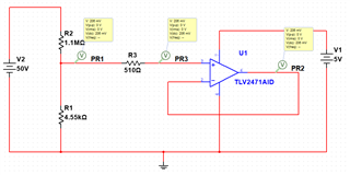
Hello, I would like to ask some questions about TLV2471, I want to measure the high voltage V2(range is 5-50VDC),so I used a resistor divider to lower the voltage V2,then connect  it to a voltage follower(TLV2471 used), the simulation schematic as shown in the figure.

When I do the actual test, I find the voltage of R1 is 0.219VDC(V2 is 50V), It is different from the calculate value and simulation result (0.206V), Because the input impedance of volage follower is very high, I think it will not affect the soure voltage, I wonder what caused the problem? Thank you very much.

In additon I have another question about  R3, I found there is a serise resistor at the non-invert input  of OPA in some design, What's the fuction of this resistor? Thanks.

  • What are the tolerances of the resistors?

    How exactly did you measure the voltage? At PR1, the input impedance of a multimeter will change the circuit.

    A series resistor like R3 protects the input's ESD diodes against high currents if the input voltage is out of range.

  • Thanks for your reply, the tolerances of resistors I uesd is 1%, the equipment is FLUKE 17B.

    Let me discribe my test procedure, When I turn off the V1,the PR1 voltage I measured is about 0.206V, then turn on the V1,  PR1 change to 0.219V, the TL471 affect the impedance of the divider?

    Another question is : through online search, I've found there is a series resister in the feedback loop of voltage follower in some circuits, the author set the resistor value equal to the input source impedance,it is to eliminate the Ios impact, is what he said true?

    Thanks for the help.Smiley

  • Hi Yu,

    some leakage current is flowing into the OPAmp input when being powered down. That's the cause of the difference.

    The so called "input bias current cancelling" resistor only makes sense when the input bias currents are high and nearly equal. In the case of TLV2471 such a resistor makes no sense, because the input bias currents are very small and can be very unequal (compare the input bias current specification with the input offset current specification in the datasheet).

    Resistors in the feedback loop of a voltage follower can make trouble because in combination with the input capacitance of OPAmp they can introduce an unwanted and destabilizing phase lag. Therefore, in faster OPAmp this technique need to be expanded by a phase lead compensation.

    You also don't need R3. R1 and R2 are enough input protection.

    Kai

  • Hi Kai,

    The leakage current I caculated is 2.857uA((0.219-0.206)/4.55*10^3), and I recheck the datasheet, the different input resistor of TLV2471 is the 12th power of 10, it much lager than R1, the difference between them is several orders of magnitude, will it cause so large leakage current (I think it may be the pA level)?

    The second question is how can I eliminate this leakage current, or I have to try different R1 to match the OPA to get the right voltage?

    Much appreciated.

  • Hi Yu,

    this leakage current flows because the input voltage exceeds the supply voltage of TLV2471. A sort of protection circuit sets in, probably an ESD cell clamping the input voltge to the rail, which allows some input leakage current to flow.

    You shouldn't allow the input voltage to exceed the supply voltage as this can destroy the OPAmp. See the "absolute maximum ratings" and "recommended operating conditions" of datasheet. And you should not expect the unpowered OPAmp work as specified in the datasheet.

    Kai

  • Hi Kai,

    Why do you say the input voltage exceeds the supply voltage of  TLV2471, I recheck the datasheet ,the indifferential input voltage range is -Vdd~+Vdd(here is 0~+5V),the common input range is also same, the Max input voltage I measured didn't exceed this range, so I can't understand it, would you explain it? Thanks.

  • Because you wrote this:

    Let me discribe my test procedure, When I turn off the V1,the PR1 voltage I measured is about 0.206V, then turn on the V1,  PR1 change to 0.219V, the TL471 affect the impedance of the divider?

    Kai

  • Hi Kai

    In the pervious reply, My question is the PR1 voltage always keep in the reasonal range(the max value is 0.219V), it didn't exceed the VDD,so I want to know why you wrote the input voltage (here 's PR1) exceed the supply voltage and cause the leakage current.Slight smile

  • Hello Yu,

    4.55k is not a standard resistance value. Can you measure the actual value of the resistors?

  • Hi,Ron

    I used two 9.1Kohm parallel resistors actually.

  • Yu,

    Is the negative lead during the voltage measurement of R1 connected to system ground or the grounded side of R1?

    At the moment, I suspect R1 might not be same ground as the measurement. You are only changing by 13mV. Make sure everything that is grounded is at the same voltage potential. 

  • Hello Ron,

    Thank you very much, I checked the circuit again, they have the same ground potential.

    I plan to test more samples to observe if others have the same problem.

  • Yu,

    At this point in time it is good to try another sample. It seems that the op amp input is raising the voltage which is not normal. You could remove R3 and see if voltage on R1 is correct and stays the same with 5V supply on and off.

    With power off, the input could accept current flow. However at 206mV, the current would be extremely low (insignificant at room temperature). The Fluke meter will load the circuit when measuring. However this would lower the voltage and the amount is not significant in this case.