A related question is a question created from another question. When the related question is created, it will be automatically linked to the original question.
If you have a related question, please click the "Ask a related question" button in the top right corner. The newly created question will be automatically linked to this question.
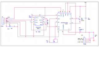
Can you share a copy of your schematic in PSPICE or in TINA? The component values are not labelled in the schematic picture you shared so it's difficult to identify exactly what is happening in the circuit. I'm especially interested in the value of C3 as it plays a role in the circuit stability, and the component values around the OPA2333 as that device must also be stable to ensure proper operation.
What is the bridge impedance of your sensor under test?
Also, what is the test setup you are using, including cabling, measurement across Rload, etc? When you say "My XTR106 giving 4-20mA" have you been able to show this using a smaller Rload value or has this not been tested?
The RLmax of the circuit is calculated as (24V - 7.5V compliance voltage) / (20mA) - Rwiring
For your application, Rlmax + Rlwiring would be 825 ohms. If the 600 ohm load resistor is being maxed out at 7V this would imply your circuit is only getting up to 11.67mA, which would suggest an Rwiring value of 814 ohms in series in your current loop, which is very high. This either suggests a problem with the test setup, or that something elsewhere in the circuit is not behaving as expected. Can you probe the Vref5 output to ensure it is a steady 5V?
The fact that your Vref is measuring 4.5V rather than 5V suggests there may be too much current being drawn from Vreg and/or Vref. Typically the OPA2333 would be powered off of Vreg (pin 1) instead of Vref (pin 14), although I'm not sure whether it would make a difference here. [Edit 9/2/21 - the Vreg output of the internal regulator should be used instead of the Vref output when powering downstream circuitry, so as to avoid potential stability issues that might occur if the internal Vref reference buffer sees significant capacitive loading] If possible, I would try powering the OPA2333 from Vreg and adding 100nF decoupling across its supplies.
When your load cell is zeroed out, are you able to get a 4mA output from the XTR106 or are you getting a different value? Also, does your load cell have a shield connection, and if so is it connected to IRET or to your main GND?
What are the values of R1, R15, R16, and the nominal sensor impedance? Can you try removing R15 and seeing what effect this has? Note in the "Bridge Balance" section of the datasheet it says "Make R2 equal or lower in value to R1", your R15 resistor is acting as the R2 but you have no R1 resistor. Please check out Kai's post here regarding proper bridge trim circuit design.
Also, what is the purpose of J4/Con2? All of those pins are floating, correct?
We are moving very slowly here, because we have to tear nearly every answer out of you. This is no fun Why is it so difficult to post a complete schematic, Atul?
Unfortunately, again it is difficult to pinpoint the issue without knowing more about the circuit. A number of factors could be at play. Assuming units of mA, a fluctuation of 0.01 to 0.05 mA could correspond to a fluctuation of 0.3413mV to 1.7064mV at Vin, due to your gain of 29.3 mA/V ( ([10k/412]+1) V/V * 2 * 40/69 mA/V ).
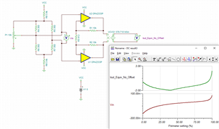
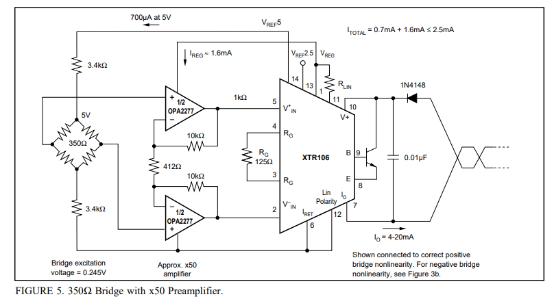
Take for example this circuit, essentially Figure 5 from the datasheet modified to more closely resemble your circuit. Note that the way your R15 potentiometer is set up, without a resistor between the bridge leg and the wiper, the potentiometer position has a serious, nonlinear effect on the offset of the bridge measurement. As you haven't provided an R15 value I just used 10k for demonstration purposes (ideally this would be significantly larger). In the below sim, the output should be in the mA range (you can think of the VCVS as performing the 40/69 mA/V conversion) but depending on the wiper position it can shift significantly. If there is instability in the wiper setting (very common with potentiometers) then it stands to reason this could result in instability of Vin and thus what looks like instability at the output.
Note too that you'd typically expect the potentiometer to be connected in parallel with the bridge, with the bottom terminal shorted to the bottom leg of the bridge rather than to the IRET. Again please see the design Kai did here - click me
From your description it sounds as though there may be a noisy environment at play. I'm assuming the 5th pin on the J2 connector is a connection to a shield on the load cell. It could be that the bridge is picking up noise and this is appearing at the XTR/OPA inputs. You could try increasing the size of the C3 cap to 0.03uF, and may want to consider adding the additional 0.01uF bypass caps shown in Figure 6 of the datasheet.
Unknown or parasitic capacitances on the circuit connected through J4 could theoretically be playing a role here as well, causing some instability or ringing behavior that will result in an AC current riding on your steady-state output, but it's hard to speculate without knowing more details.
please wire the XTR106 exactly as shown in the datasheet:
So use "Vref5" and "Vreg", "Vref5" for the load cell and "Vreg" for the OPA2277.
Remove the pot R15 because the way you have connected it to the circuit is completely wrong.
The load cell, the OPA2277 and the XTR106 must be mounted close together. Don't allow any cabling here.
If you still have unexplainable noise at the output of XTR106, add 10nF low pass filter caps from both inputs of OPA2277 to the ground pin of OPA2277 (which is "Iret"). And mount these two caps close to the OPA2277.
If you still notice noise at the output of XTR106, add some shielding of load cell and input circuitry and connect the shield to "Iret". But be careful with all these measures because Iret is not true signal ground but is a floating auxiliary potential. So if anything of the input circuitry (load cell, shielding) could be touched during normal operation, then make an isolation arround the circuit and the shield. Otherwise you can get trouble with ESD, Surge and Burst (EFT).
The same is valid when you are doing measurements and must touch Iret with the ground terminal of DMM. Simply by this you can inject so much EMI and noise that the circuit appears to be noisy, although it isn't noisy at all.
If you need to touch the outputs of OPA2277 with the DMM, don't do it directly but insert a 100R isolation resistor which you mount close to the output of OPA2277. This is necessary to avoid instability.
Thanks for sharing the component values, this is definitely helpful. I'm interested to hear whether removing the potentiometer helps with your circuit stability. As I mentioned before a 10k pot is small enough that a small deviation in its setting could lead to a large change in your circuit output, so if you do want to employ an offset trimmer you'll want to use a much larger value (and connect it truly in parallel with the bridge, between the 3.2k limiting resistors).
I agree with Kai's comments above, especially regarding the circuit isolation if the shield is tied to IRET and exercising proper caution when probing the circuit to avoid injecting noise. Let us know how it turns out.