This thread has been locked.

If you have a related question, please click the "Ask a related question" button in the top right corner. The newly created question will be automatically linked to this question.

OPA211: General input offset voltage question

Part Number: OPA211
Other Parts Discussed in Thread: OPA1622

Hi,

In reading the document "An Engineer's Guide to Designing with Precision Amplifiers" a question has come up regarding the contribution to input offset voltage made by the PSRR of the device.

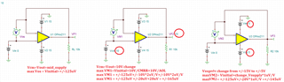
On page 10, section "How to interpret an op amp’s offset voltage specification and test conditions", the input offset voltage for the OPA211 device is discussed.  The OPA211 data sheet does not specify input offset voltage over a range of supply voltages; rather, it specifies it at a single operating voltage of +/-15V.  Further down, below figure 4, the document says: "Changing the supply voltage of the OPA211 from ±15 V to ±10 V introduces an additional offset voltage because of the device’s PSRR specification (±1 µV/V)" and equation 1 then shows that this additional offset voltage is +/-10uV.  The additional offset voltage is then added to the initial (data sheet value at +/-15V) offset voltage to obtain the worst case offset voltage.

Now, this is referring to DC input offset and the implication is that, as you decrease the operating voltage below +/-15V (decrease magnitude), the input offset voltage worsens (increases magnitude). This is hard for me to digest as it is counter-intuitive. Take a different device, for example, the OPA1622.  Here, the data sheet specifies the average (+/-100uV) and maximum offset voltage (+/-500uV) over an operating voltage range +/-2V to +/-18V. So we can be sure (to a 3 sigma probability) that at any operating voltage within the specified range, the offset voltage will not exceed +/-500uV.  An alternative way of phrasing this for the OPA1622 is that, at DC, the contribution to the offset voltage made by the device PSRR is zero.

Back to the OPA211, the combination of a single data sheet value for offset voltage taken together with the discussion in the document, would mean that the offset voltage value specified at +/-15V is the best case possible; any deviation from that operating voltage will increase the magnitude of the offset voltage with the worst case being at the lowest operating voltage (+/-2.25V, 150.5uV offset voltage).

Is this the right way to interpret the data sheet data?

Regards,

AC

  • The input voltage offset, Vos, of most op amps shown in datasheet is specified under default conditions - typically, Vin=Vout=Vcc/2 (see at the top of the datasheet table page) and thus you need to think of it only as Vos_initial BEFORE you change any condition from specified default values like Vout, Vcc or Vcm. 

    Below please see definitions of AOL, PSRR and CMRR which are all function of changing Vos:

    AOL=ΔVout/ΔVos_aol  ->  ΔVos_aol = ΔVout/AOL

    PSRR=ΔVcc/ΔVos_psrr  -> ΔVos_psrr = ΔVcc/PSRR

    CMRR=ΔVcm/ΔVos_cmrr  -> ΔVos_cmrr = ΔVcm/CMRR

    For this reason, the actual total offset voltage at 25 deg C, Vos_total, is composed of four components:  

    Vos_total (25C) = Vos_initial + ΔVos_aol + ΔVos_psrr + ΔVos_cmrr

    where Vos_initial is the offset value specified in the datasheet at 25C, Vos, and the additional components MUST be added under specific conditions as you change them from specified default values. Since most of the offset components are uncorrelated with each other, they actually should be added as vector quantities (square-root of squares).

    All of the input offset voltage components shown above apply at 25C and may change over temperature variation.

  • Hi Marek,

    Thank you for your response. However, my question was about static DC conditions. No input signal. No power supply delta. Constant load. The article that I referenced suggests, unless I'm reading it wrongly, that if I choose to power an OPA211 at +/-15V then the input offset voltage will be +/-125uV max but if I choose to power the device at +/-10V then the input offset voltage will be +/-135uV max.

    That is what I don't understand.

    Kind regards,

    AC

  • AC,

    All of the above equations are for DC conditions.  There is always an input voltage even if it is 0V.  Looking at the OPA211 below it shows max PSRR of 1uV/V (min 120dB) and min AOL and CMRR of 114dB (max 2uV/V). Using these specification together with the change in Vcm, Vout and/or Vsupply from its initial datasheet conditions (Vcm=Vout=0V, Vsupply=+/-15V) will give you max total_Vos - see below.

    See below what this means in terms of changing total_offset under different conditions - see below.

    If you power OPA211 on +/-15V supplies with Vcm=Vout=0V (mid-supply), these are exact default conditions used to test the part and thus +/-125uV applies. Now, if you change the supplies from +/-15V (total supply of 30V) down to +/-10V (total of 20V), you will increase the offset due to PSRR max limit of +/-1uV/V resulting in offset change, ΔVos_psrr = ΔVcc/PSRR =(30V-20V) * (+/-1uV/V) = +/-10uV.

    Thus, Vos_total (25C) = Vos_initial (25C) + ΔVos_psrr (25C) = +/-125uV +/-10uV = +/-135uV

  • Hi Marek,

    Thank you for the detailed explanation. I Understand now.

    Regards,

    AC

  • Glad to hear it - good luck.