This thread has been locked.

If you have a related question, please click the "Ask a related question" button in the top right corner. The newly created question will be automatically linked to this question.

XTR115: Cable positioning influences capacitive sensor reading

Part Number: XTR115

Dear support,

Many thanks for the excellent support last time, this fully solved the question I had.

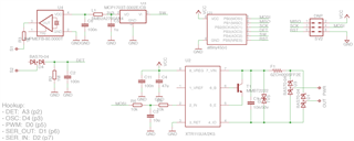
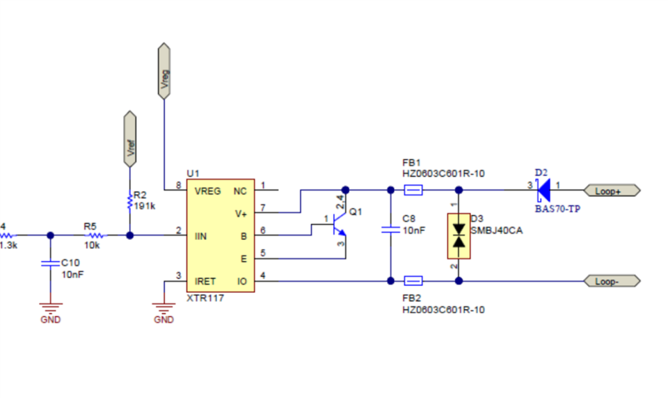
I have another issue that is related to this design: The attached schematic measures capacitance between the two sensor pins (schematic is slightly updated, see attached).

The issue is that when I have multiple devices in parrallel, the positioning of the cables close to one another or with space in between has influence on the measured voltage alter the diode (sensors themselves are separated by distance). Would this be some kind of capacitive coupling? Would you have any idea of what would cause this and how I might be able to solve this issue?

Thanks in advance!

Hans Crijns

  • Hi Hans,

    at 100MHz the cables turn into antennas and begin to radiate and to receive. The circuit no longer works electrostatically but begins to work electrodynamically. You should insert individual chokes into each 4...20mA line or thread each 4...20mA signal pair through a ferrite sleeve forming a common mode choke. The chokes or ferrite sleeves should have an impedance maximum at 100MHz.

    Kai

  • Hi Hans,

    I agree with Kai, the 80MHz oscillators are likely causing problems with radiated emissions. This may be worsened by the absence of a ground plane, which would otherwise help with shielding. I see you have an inline fuse F1, but you should add some Ferrite beads as well. We have a TIPD that used two ferrite beads for EMI protection and it did well on IEC 61000 4-3 and 4-6 (see schematic on page 27, and test results pages 19 and 23). 

    You might also consider moving your C3 cap to get better filtering, as shown in this image (please excuse my poor MS Paint skills). You basically want the actual signal path routed directly through the pad, instead of having a skinny trace running to the cap. Adding an additional 10nF decoupling cap between Vin and IRet could potentially yield a minor benefit in terms of protecting against noise on the XTR inputs.

    It also looks like U4 could be rotated 180 degrees, which would allow you to shorten the distance from the VCC pin to the decoupling cap in accordance with that part's datasheet. Again, you want that cap as close to the device as possible (shortest signal path) to maximize its effect.

    Cheers, 

    Jon

  • Hi Jon, Kai, 

    Many thanks for your fast response and clear pointers. I was expecting indeed the 80Mhz to be causing the issues.
    I did test with a ground plane and ferrite beads (not both at the same time) and it did reduce the issue a bit, but not fully/enough. I will test your suggestions together in the coming days.
    Two more questions:
    - The oscillator is generating a square wave and therefore higher harmonics. Would that be an issue? Would you know a way to reduce these harmonics?
    - Would you expect the best performance with the ground plane under the full PCB, just the XTR115 part or oscillator+attiny part?
    Thanks,
    Hans 
  • Hi Hans,

    yes, low pass filtering of 80MHz square would help. I would add a low pass filter after the oscillator and a buffer to avoid any impact of the moist medium you want to measure on the filter curve, as the moist medium looks like a varying capacitance.

    Unfortunately, with additional electronics you will run into supply current issues because the supply current you can pull out of the XTR115 is limited.

    You could try to add a small inductance of 56...100nH to the output of square wave oscillator and see whether it helps.

    Kai

  • Hi Jon,

    Tested with two beads in the in/output lines and this improved things a lot. Added a GND plane (with copper tape) below the attiny and oscillator and changed the position of the 47uF cap in the LPF that improved things even more. Thanks for the good suggestions! 

    Have now closed the issue.

    Thanks, Hans

  • Hi Hans,

    I'm glad to hear this helped resolve the issue. Feel free to reach out again if you have any further questions!

    Cheers,

    Jon