This thread has been locked.

If you have a related question, please click the "Ask a related question" button in the top right corner. The newly created question will be automatically linked to this question.

OPA188: How to measure the offset voltage

Part Number: OPA188

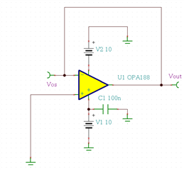
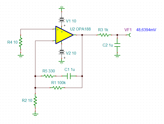
I made a circuit like the one shown in the figure and actually measured it, but the offset voltage was too small to be confirmed with an oscilloscope. I would like to know if there is a measurement method that can be used with a measuring instrument that cannot measure minute values like an oscilloscope.

  • Hi Ryu,

    I would do it this way:

    ryu_opa188.TSC

    In this circuit the input offset voltage of OPA188 is multiplied by a factor of

    100k/10 + 1 = 10001

    So, the input offset voltage of OPA188 in the above simulation would be about

    48.6mV / 10001 = 4.9µV

    Please note that up to about +/-0.4µV measuring error can occur due to the input bias current of OPA188.

    C1 reduces the bandwidth of the circuit and heavily reduces noise. R5 is necessary to prevent an erosion of phase margin and helps to keep the circuit stable.

    R3 and C2 form an additional low pass filter.

    Keep in mind that measurements with ultra low input offset voltages can be very tricky. The circuit must be shielded by Faraday cage being connected to signal ground. Also, thermoelectric potentials can play a role. The soldering must therefore be carried out very carefully and any air flow across the circuit during the measurement must be prevented. So the Faraday cage plays a double role. And allow the circuit some minutes to fully thermally stabilize and to find an thermal equlibrium.

    Kai

  • You could not possibly be able to measure few macro-volt offset in a buffer configuration and thus Kai's approach using high gain with filtering is a very good one. The only thing I'd like to add here is that many chopper amplifiers like OPA188 may need R4 shown above to match the input impedances between the input terminals (R2||R1=~10ohm) in order to eliminate the commutation of the IB spikes across unmatched input impedance.