This thread has been locked.

If you have a related question, please click the "Ask a related question" button in the top right corner. The newly created question will be automatically linked to this question.

XTR116: What additional components are absolutely necessary & any project advice :)

Part Number: XTR116
Other Parts Discussed in Thread: XTR115, XTR111

Hello!

I made the silly mistake of ordering a XTR116 without properly reading the datasheet and now i have no external transistor which i definitely need.

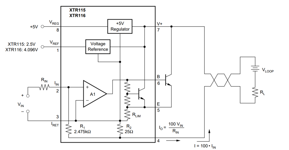
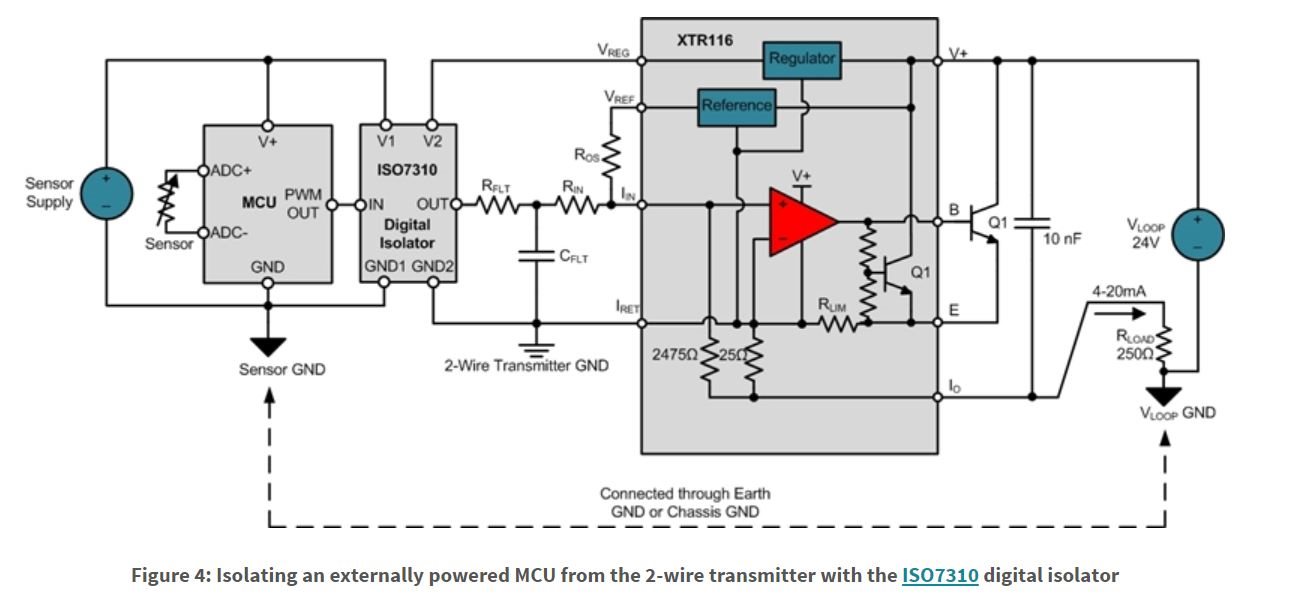
Im struggling to understand the role of the resistor between Vref and Iin and in understanding if any other components are required.

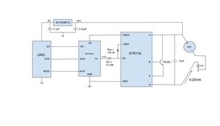
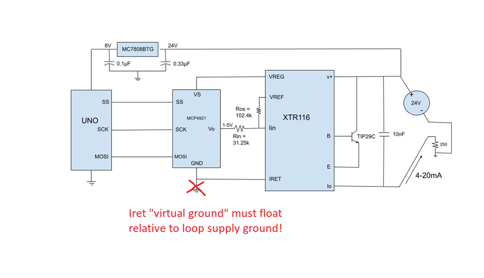
The project that i am working on uses an Arduino to send sine wave values over SPI to a DAC (MCP4921) which will then output values 1V-5V.

I would like to use this to generate the 4-20mA current loop.

I understand i can do this using an op amp and resistor but ive already done that and would now like to try out the XTR116. 

I have a feeling the dac is unnecessary in this new circuit but im not 100% so i would appreciate any advice.

Thanks! 

  • Hi Wasp,

    the internal OPAmp A1 of XTR116 always keeps -with the help of its internal feedback loop- the "Iin" input (pin 2) at the same potential as the "Iret" terminal (pin 3). So pin 2 is actually a current input which lies on "virtual Iret".

    Kai

  • By the way, how do you want to supply the microcontroller and DAC? By the XTR116 or by an external supply? In the first case the current that can be drawn from the Vreg pin of XTR116 is limited to about 2.5mA. In the second case you would need a galvanic isolation between the externally supplied circuitry and the circuitry powered from the XTR116.

    Kai

  • Hello Wasp,

    I highly recommend checking out this FAQ (click me) that our own Katlynne Jones put together, it is full of helpful links that can demystify the workings of 4-20mA transmitters. I especially recommend the series of Precision Labs videos, starting here (click me). I know that personally I struggled to understand how the "floating" ground on such a system works in addition to the other nuances of these circuits, and found the series quite helpful.

    The resistor between Vref and Iin is used to provide an offset. As Kai mentioned, Iin ~= Iret due to the internal amplifier feedback. Thus, the resistor between Vref and Iin is basically a parallel offset current that acts in addition to the current from Vin. Iout of the transmitter is 100*Iin = 100 * Vin/Rin, so if you have an offset like this then Iout is 100*In = 100*(Vin/Rin + Vref/Roffset). Usually this is used to establish a 4mA offset, which allows a budget of 4mA to power the XTR116 itself, as well as any downstream circuitry or sensors powered by Vreg and Vref. In terms of other components needed, it depends what you are worried about (TVS diodes for ESD protection, and a series diode or diode bridge to protect against accidentally connecting Vloop and Iret backwards, are commonly implemented), but at the very least you should put a 10nF decoupling cap between Iout and V+ as shown in Figure 1 of the datasheet.

    I'm attaching a behavioral TINA model of the XTR115/116 that shows how the XTR generally works and makes it easy to play around with different component values and see their effect. It is neither functionally perfect, nor does it cover all of the limitations and peculiarities of the device, but it's a good place to start. Note that as Kai said the XTR can only supply about 2.5mA from its Vreg pin (otherwise the Iout cannot go down to 4mA anymore but will get "stuck" at a higher current, say 5mA if you tried drawing 3.5mA from Vreg), and this is an example of something not reflected in the model.

    3872.4-20mA Loop Analyzer.TSC

    I'm not certain I understand how your circuit is intended to function with the DAC/Arduino, can you share a system block diagram or similar? Also keep in mind the XTR116 will need a fairly high voltage loop supply (look for the parts of the video series that discuss "compliance voltage" for an explanation of the specifics) and you'll need to be very careful with regards to grounding (Iret should never be tied to a fixed external GND voltage, it needs to float). There are a lot of considerations to be made when designing with XTRs and it's better to go slow, rather than jumping right in and risking inadvertently frying your parts!

    Cheers,

    Jon

  • Hi, Thank you both for your comments and suggestions. As requested here is my block diagram. I found both of your explanations of the off set resistor very helpful. I'm still not fully sure I understand the concept of floating ground I will have a look into the video series you have linked. If you have any more advice that would be great.

  • Hi Wasp,

    It looks like the DAC you want to use would be fine powered off of the Vreg of the XTR116, but you will not be able to power the Uno from the 24V loop supply and ground it in the fashion you have shown. It comes down to the "virtual" or "floating ground" principle.

    Basically, IRET cannot be tied to a fixed ground voltage. Remember that the transmitter current signal is equivalent to the voltage across the load resistor (250 ohms above) divided by that resistance. The current out of the device will thus dictate the voltage at the Iout pin, so naturally the voltage of this pin must be allowed to move around, right? Well, in order for the Iout voltage to move around, the Iret voltage also has to be able to move around (I encourage you to take a look at the behavioral model I shared to see how this works and how the various current paths are balanced). If it's fixed, then you have no way of changing the output current.

    Now, the Vreg voltage from the XTR116 will also shift to maintain a level 5V above the voltage at the Iret pin. Therefore, any "downstream" device that uses Vreg for its supply voltage and Iret for its "GND" connection will see a consistent 5V supply. The problem is the Vreg of the XTR116 can only drive so much current, so you can't run the Uno off of it. If you then powered the Uno off of the 24V loop supply and used the loop ground as the Uno ground, you run into a problem where the Uno is referenced to one voltage (loop ground) but the DAC and the XTR116 input are referenced to a different voltage (Iret). This will cause major problems.

    The solution? Isolation between the Uno and the DAC, or between the DAC and the XTR116. This allows you to keep the grounds separate, as shown below.

    This particular FAQ addresses this case in detail, and includes some example part numbers for the isolation to start with, but again I'd encourage you to watch that Precision Labs series I linked as well. Note that using a three-wire transmitter like the XTR111 would also be an option here, should you be interested.

    Cheers,

    Jon

  • Hi Wasp,

    as JMac already mentioned the voltage regulator section will not work. You would force a current to flow into the "Iret" pin which isn't sourced by the XTR116's "Vreg" or "Vref" pin. This will ruin the internal feedback loop and cause errors.

    You might want to also read this thread:

    e2e.ti.com/.../xtr116-incorrect-reference-voltage-and-malfunctioning-4-20ma-output-driver

    Kai