This thread has been locked.

If you have a related question, please click the "Ask a related question" button in the top right corner. The newly created question will be automatically linked to this question.

OPA615: Video clamping IC or video buffer with DC restoration function

Part Number: OPA615
Other Parts Discussed in Thread: OPA361, OPA360, OPA362, THS7303, THS7353, THS7347, THS7327, THS7316, THS7365, THS7373, THS7368, THS7364, THS7372, THS7360, THS7376

Hi Team,

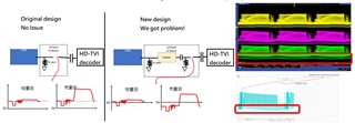
Recently, we met an issue that the video signal DC part is removed by adding ground isolator. For the video signal, it must be included DC content. So, do you have any suggestion of the video buffer with DC restoration? The function is like DIODES ZXFV4089.

The bandwidth must cover 50MHz. Our application is HD-TVI with 1080p 60Hz.

I find OPA615 ,but if there is any part can fulfill our requirements, please let me know. Many thanks.

Roy

  • Hello Roy,

      If they are not able to DC bias the input of the amplifier or reference the output of the amplifier to DC voltage, then an amplifier with a Vref pin or DC restore function would be needed here. OPA615 is a good find, also look into:

    1. OPA360/OPA361/OPA362 (internal level shifter, sag correction, and AC coupling capacitors (2-Pole Filter), but <10MHz bandwidth)

    2. THS7303 (internal selectable filters up to 190MHz, sag correction, AC/DC input bias mode, DC bias/level shift/restore) 

    3. THS7353 (internal selectable filters up to 150MHz, sag correction, AC/DC input bias mode, DC bias/level shift/restore) 

    4. THS7327/THS7347 (internal selectable filters up to 500MHz, sag correction, AC/DC input bias mode, DC bias/level shift/restore) 

    5. THS7316/THS7365 (internal selectable filters up to 36MHz, AC/DC input bias mode, DC bias/level shift/restore) 

    6. THS7373  (internal selectable filters up to 350MHz, AC/DC input bias mode, DC bias/level shift/restore) 

    7. THS7368/THS7364/THS7372 (internal selectable filters up to 72MHz, AC/DC input bias mode, DC bias/level shift/restore) 

    8. THS7360  (internal selectable filters up to 70MHz, AC/DC input bias mode, DC bias/level shift/restore) 

    9. THS7376  (internal selectable filters up to 300MHz, AC/DC input bias mode, DC bias/level shift/restore) 

      I highlighted in bold the devices I would recommend for 50MHz, HD-TVI 1080p 60Hz application.

    Thank you,

    Sima 

  • Hi Sima, 

    Thanks, Roy is my TI FAE contact, and I have further design questions here, let me describe the issue below

     ============================================================

    Our product is infotainment, and plays the HD-TVI receiver role in the video signal chain.

    I met an issue that our ground isolator (OP amp) in front of the decoder removes HD-TVI’s DC content, and makes the camera video swinging during dark and bright environment as below diagram shown. Furthermore, the swinged signal affects the HD-TVI decoder AGC mistake that treat sync tip as attenuated, and drives AGC gain larger and larger.


    To make the circuit right, we studied the clamping circuit method trying to clamp the swinged signal to correct level and stabilized. But a simple diode method (easy to implement by BOM change) somehow impact the color burst negative part due to our PCB ground issue. Then, we noticed THS7372 might be the solution to this issue.


    So, here’s my questions.

    1. Is THS7372 the right solution that put at my ground isolator output?
    2. What is the input mode defined in the datasheet of my application? AC SYNC TIP CLAMP?
    3. What is the output mode of my application? DC-COUPLEED?
    4. What design guideline we need to know about this issue? We are not familiar with analog video


    Thanks,

    Nick.


  • Hello Nick,

      Thank you for providing details on your application. 

    1. The THS7372 will fix your issue with a total of 300mV DC shift to compensate for ground isolator. However, just to be sure you do not violate input/output common mode range of the device, what is your max and min input voltage as well as max/min output voltage you are looking for? This device has an internal fixed gain of 2V/V or 6dB. 

    2. You are correct, input mode for your application would be the AC Sync Tip Clamp. The series capacitor + isolator would mean AC coupled, but since you won't be setting an external input bias to the application, you would need to use the AC Sync Tip Clamp input mode operation. This will automatically set the min input voltage to 0V reference, which then will go from a 150mV level shifter (will become 300mV above 0 after fixed gain of 2V/V). If the input voltage is below 0V which you have shown in the left case of the image, then THS7372 internal control loop sources up to 6 mA of current to increase the input voltage level on the THS7372 input side of the coupling capacitor. As soon as the voltage goes above the 0-V level, the loop stops sourcing current and becomes very high impedance. So, this device acts like an automatic dc restoration circuit. 

    3. If you are not using output series coupling capacitors, the output mode of you application would be DC-Coupled. Looks like here, you want to continue keeping the DC reference for your application, so yes you would want to DC couple the output and not add series coupling capacitors at the output of the amplifier.

    4. I would follow the sections on input mode/ output mode in device datasheet and make sure the application does not violate input/output common mode ranges. I have linked some more information on video designs using our amplifiers here

    Thank you,

    Sima

  • Hi Sima,

    Thanks! THS7372 helps our issue! The AC sync tip is go above 0V steady.

    But since we have many video accessories, when we switch between them, the screen is rolling from bottom to top. I wonder it is caused by DC level difference? How can I adjust the DC level shift of THS7372?

    Regards,

    Nick.

  • Hello Nick,

      I am glad the THS7372 solved your earlier issue! 

      When you say switch between these video accessories, is the screen rolling from bottom to top only happening when the THS7372 is fed the input signal or when the amplifier is powered on, or is it a constant issue? 

      For DC offset, internal 300mV shift is the highest out of our video amplifiers. Unfortunately, you would need to add DC shift external to the device either at the input of the amplifier after the AC coupling capacitors or at the output of the amplifier. 


    Thank you,

    Sima 

  • Hi Sima,

    Sorry for the late reply. The screen rolling issue looks like video decoder issue, not caused by THS7372 DC restore IC.

    But, do you have any suggestion DC restore IC that we can adjust the level shift?

  • Hello Nick,

       Hopefully, the video decoder issue is an easy fix. For adjusting the internal DC level shift, this unfortunately will not possible unless an external shift is used. The 150mV voltage shift, gained by 2 is a total of 300mV voltage shift at the output which is the highest with our selection of video amplifiers. If the application requires a higher shift, you could add an external reference either to the input or the output of the amplifier after the AC coupling capacitors. 

       Below is an example on how to add an additional external DC shift at the input of the amplifier, or you could add this at the output of the amplifier. 


      An easy, but not as precise as using a dedicated voltage reference, would be to use a voltage divider using the power supply rails of the amplifier.

    Thank you,
    Sima