This thread has been locked.

If you have a related question, please click the "Ask a related question" button in the top right corner. The newly created question will be automatically linked to this question.

INA226: schematics reviewed for the negative voltage sense

Part Number: INA226
Other Parts Discussed in Thread: TIDA-00313, INA238

Hi Sir,

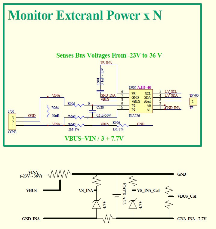
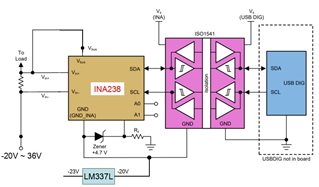
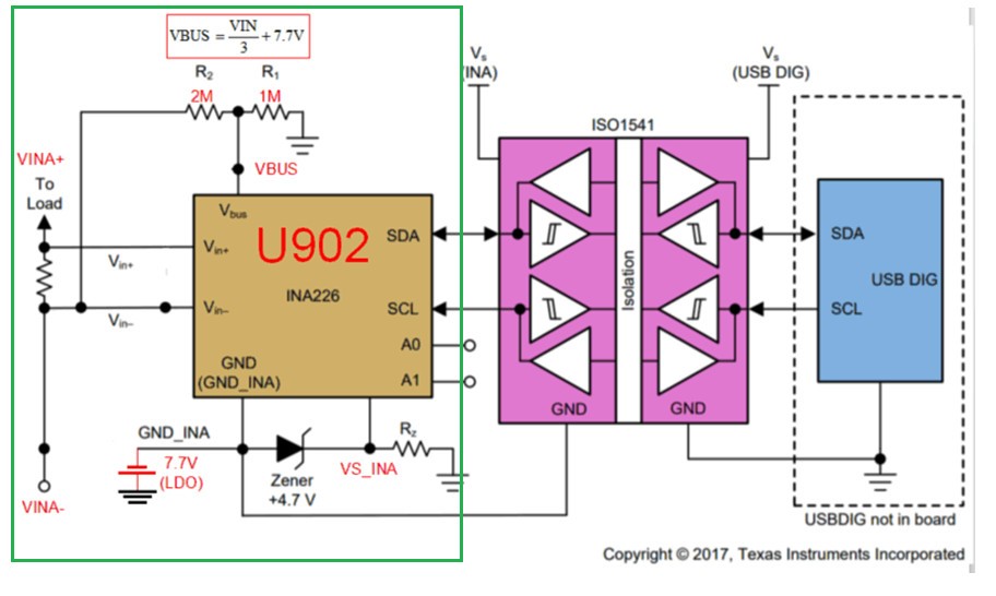
My customer refer to the TIDA-00313 Basic Block Diagram to do the INA226 application circuits for voltage sense from -23V to +36V.

Could you please help to review the schematics is available or not?

Programmable power system_V1_0924.pdf

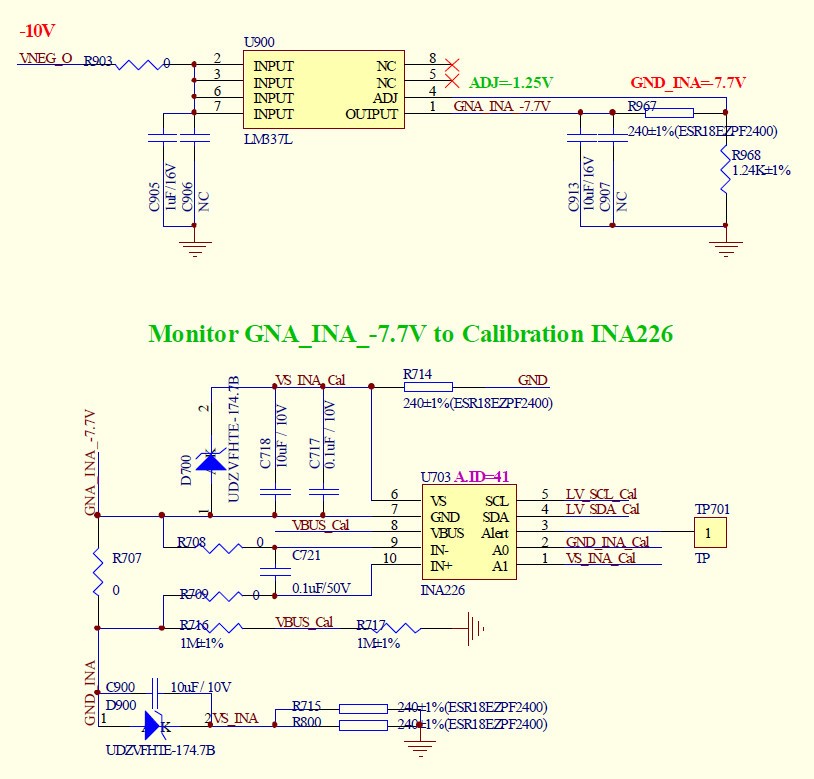
*The U702 is monitored the net-name "GNA_INA-7.7V" is equal the -7.7V or not.

And the net-name "VS_INA" is 4.7V.

*The voltage sense circuit from -23V to +36V.

  • Hello Henry,

    I see two issue with this design.  The first is the GND_INA pin must be the same voltage as the lowest voltage of VBUS or Vin+ and Vin-.  From the TIDA-00313 you can see it is connected to -48V.  So from your example it should be -23V as that is the lowest voltage.

    The other issue is the VCM Range.  For the INA226 the VCM range is from 0 to 36V this is relative to the GND_INA pin.  So you can only go 36V above the GND_INA pin.

    If you are able to connect the GND_INA pin to your lowest voltage possible of -23V you could use the INA238 in its place as it has the ability to go 85V for the VCM voltage above the GND_INA pin.

    Regards,

    Javier Contreras

  • Hi Javier

       The black diagram as below , the voltage range is from -20V to 36V ,  Is the black diagram OK?

  • Hello,

    That looks correct.  Make sure the GND_INA never goes above the Vin or Vbus voltage.