This thread has been locked.

If you have a related question, please click the "Ask a related question" button in the top right corner. The newly created question will be automatically linked to this question.

LM2903B: Customer encounters issue when replacing LM2903 with LM2903B

Part Number: LM2903B
Other Parts Discussed in Thread: LM2903, LM393

Hi team,

My customer has encountered output issue when replacing LM2903 with LM2903B. There is no any other change besides the comparator bom change.

Please see the normal waveforms (LM2903) and abnormal waveforms (LM2903B) as below,

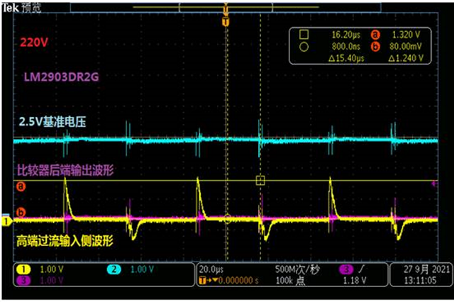
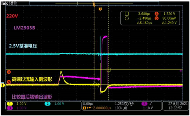
Channel 1: input signal of pin5; Channel 2: input signal of pin6 (2.5V reference voltage); Channel 3: output signal of channel 7.

The supply voltage for the comparator is 5V while the pull-up resistance is 4.7kohm.

The first figure works well but in the second figure, LM2903B's output has abnormally flipped even though the channel one voltage hasn't override the reference voltage.

This is mature design in my customer side and this phenomenon works only with LM2903B. On the same board, once the device is changed to LM2903 again, this issue will be solved.

Please help give advise. Thanks!

Regards,

Xiaoying

  • Hello Xiaoying,

    It seems that the LM2903B is more sensitive to the negative input voltage in this application. The input voltage on pin 5 (+IN) is going almost -0.5V below V-. Abs Max is -0.3V. Reversals and glitches are a common result of exceeding the negative voltage range.

    Please see section 2.6 of the LM393 family appnote:

     Application Design Guidelines for LM339, LM393, TL331 Family Comparators

    They will need to either add a diode clamp and series resistor, or, switch back to the non-B version. We really recommend adding the resistor and diode.

  • Hello Paul,

    Thanks for your kind response. Here is our schematics design for you reference.

  • Hi Paul, 

    Please have a look at Jimmy's response of the schematic and suggest if it is available to do some bom/minor change on the board to try some test and solve the LM2903B issue.

    This case is a little urgent and need your support to see whether they can use the same board to support both LM2903 and LM2903B. Thanks!

    Regards,

    Xiaoying

  • Hi Jimmy,

    What is the maximum voltage on the left side of R127? Is it really 220VAC??

    What is the "normal" operating range, and the expected maximum?

    Confirm that the comparator supply voltage is also 5V.

    Two issues:

    The Zener diode has a conventional -0.6V reverse voltage, as opposed to the recommended Shottky that would be in the -0.3 to -0.4V range.

    The valid upper input range of the LM2903 is Vcc - 2V, or 3V on a 5V supply. The Zener is 5V, which exceeds the input range. Please see section 2.2 of the above appnote.

    To get -0.5V on the input, you have to be pulling several mA worth of current. IF it really is 220VAC, then that is ±311V, which is ±41mA.

    For a simple BOM change, I would try increasing the values of R127 and R128 by 10x, to 75k and 10k (and reduce C81 to 100pF). That drops the peak current to 4mA.

    If they can change the board, I would add a Schottky diode in parallel with the Zener to limit the negative peak.

    The LM2903 can withstand a voltage as high as 36V on the input, regardless of supply voltage, so the Zener could be replaced with a Shottky if the maximum voltage at the input pin is under 36V.

    BTW: Be sure they check the power and voltage rating of R127..particularly if they are small SMT resistors. Usually dividers off the line voltage are in the 100's of k and consist of several resistors in series to spread out the voltage across each resistor.

  • Jimmy

    There has been no further input on this thread, so it will be closed.  If you need further support, please feel free to respond or open a new thread.

    Thanks, Chuck