


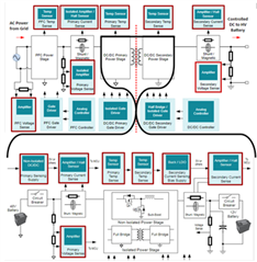
On-board charging systems (OBCs) manage the flow and conversion of AC power from an external charging source to the vehicle’s battery as DC voltage. While doing so the system must sense for irregularities and potential safety pitfalls.
A DC-DC converter is a circuit that is either stepping down or stepping up DC voltage. In the case of HEV/EV the DC-DC converter is generally stepping down the DC voltage freshly converted by the OBC to a manageable 1V rail that will be able to power a majority of the electrical functions within the cabin.
As such the OBC and DC-DC circuit are two sides of the same coin, interwoven to manage the journey of energy from the charging source to the vehicle’s internal functions. With such close proximity and similarity in amplifier requirements for sensing functions these recommendations can be given as a pair. It is important to note whether the devices are for a socket on the high-power side, before DC-DC conversion, or on the low side, after DC-DC conversation, as this will determine the voltage range and supply precautions required for the amplifier.
Current Sensing:
One of the most important functions of current sensing circuits is to identify leakage current and do so as quickly as possible. Furthermore, should an overload recovery take place a fast amplifier response is vital to maintain system efficiency. For this an amplifier needs a fast settling time and should have a high slew rate and a wide bandwidth.
Table 1: Precision amplifier recommendations for current sensing opa388-q1 opa320-q1 opa365-q1
|
Number of |
Vs min |
Vs max |
GBW typ |
Slew Rate typ (V/µs) |
Vos max |
|
|
OPAx388-Q1 |
1,2 |
1.8 |
5.5 |
10 |
5 |
0.005 |
|
1,2 |
1.8 |
5.5 |
20 |
10 |
0.15 |
|
|
OPA365-Q1 |
1,2 |
2.2 |
5.5 |
50 |
25 |
0.2 |
If the current sensing circuit is on the secondary side it may require post processing from an isolation amplifier. In this scenario the isolation amplifier's output may need further amplification without degrading the CMRR. In such cases, an instrumentation amplifier like the INA333-Q1 is an adequate solution. Often, an isolation amplifier is limited in gain and cannot amplify signals to a desirable level. A difference amplifier can be used for such a function. However, with difference amplifiers, the input impedance is low. In case where a high impedance is needed, an instrumentation such as the INA333-Q1 can be used to resolve small signal in the presence of large common mode voltages. Given its stellar performance, the INA333-Q1 can reduce common mode errors thanks to its 96dB (Min) of CMRR.
Table 2: Instrumentation amplifier recommendations for current sensing ina148-q1
|
Package (Single channel only) |
Vs min |
Vs max |
CMRR min |
Iq typ |
Vos max |
|
|
INA148-Q1 |
SOIC(8) |
2.7 |
36 |
70 |
.6 |
5 |
|
INA333-Q1 |
VSSOP(8) |
1.8 |
5.5 |
96 |
.05 |
0.025 |
Voltage Sensing:
When it comes to voltage sensing speed becomes much less of an issue and instead a precise result is valued to avoid any sort of damage to the system. It is a common misbelief that sensing circuits will need a calibration regardless of offset so precision parts aren’t required to achieve an accurate result. Offset calibration is standard and not incredibly complex, however; calibrating for offset drift is non-trivial and may require an additional two or three points of calibration, which costs time and funding. As such its important to identify amplifiers with low offset voltage and offset voltage drift.
Table 3: Primary side amplifier recommendations for voltage sensing opa376-q1 opa377-q1
|
Number of |
Vs min |
Vs max |
Vos max |
Drift typ |
Vn typ |
|
|
OPAx388-Q1 |
1,2 |
1.8 |
5.5 |
0.005 |
0.005 |
7 |
|
1,2,4 |
2.2 |
5.5 |
0.025 |
0.32 |
7.5 |
|
|
OPAx377-Q1 |
1,2,4 |
2.2 |
5.5 |
1 |
0.32 |
7.5 |
If the voltage sensing circuit is located on the secondary side of the OBC it may be beneficial to design around higher voltage amplifiers that can take advantage of the ubiquitous 12V rail without the need for additional step downs.
Table 4: Secondary side amplifier recommendations for voltage sensing opa197-q1 tlv197-q1
|
Number of |
Vs min |
Vs max |
Vos max |
Drift typ |
Vn typ |
|
|
1,2,4 |
4.5 |
36 |
0.25 |
0.5 |
5.5 |
|
|
TLVx197-Q1 |
1,2,4 |
4.5 |
36 |
0.5 |
1 |
5.5 |
Temperature Sensing:
Temperature sensing has looser requirements than voltage or current as minor temperature variation has significantly less impact on a system than variation in current or voltage. When designing for this function a higher voltage amplifier will enable wider temperature measurements, particularly important as the circuit heats up towards its upper limit. Furthermore, choosing an amplifier with low offset voltage drift will again prevent the need for additional calibrations saving time and effort using complex algorithms.
Table 5: Amplifier recommendations for temperature sensing opa192-q1 opa197-q1
|
Number of |
Vs min |
Vs max |
Vos max |
Drift typ |
Vn typ |
|
|
1,2 |
4.5 |
36 |
0.025 |
0.1 |
5.5 |
|
|
1,2,4 |
4.5 |
36 |
0.25 |
0.5 |
5.5 |
|
|
TLVx197-Q1 |
1,2,4 |
4.5 |
36 |
0.5 |
1 |
5.5 |
For useful resources and additional information, please make sure to check out the following content:
Voltage and current sensing in HEV/EV applications (Technical Article)
Understanding current sensing in HEV/EV batteries (Technical Article)
OBC Reference design (Reference Design)
DC-DC Reference Design (Reference Design)
OBC EE Slides (End Equipment Slides)
DC-DC EE Slides (End Equipment Slides)
