This thread has been locked.

If you have a related question, please click the "Ask a related question" button in the top right corner. The newly created question will be automatically linked to this question.

OPA656: Peak Detector (2MHz) does not function

Part Number: OPA656
Other Parts Discussed in Thread: OPA356, , OPA357

Hi,

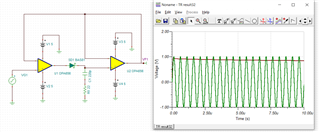
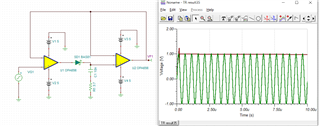
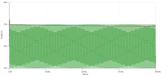
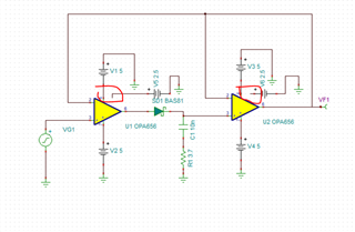
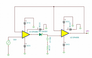
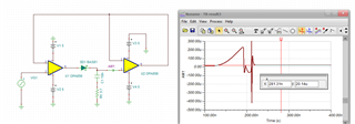
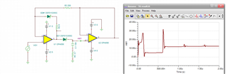
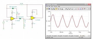
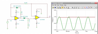
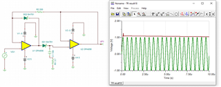
I am trying to build Peak Detector for 1V 2MHz signal using OPA656. I want to use +-5V supply instead of +-2.5V. Same circuit works with OPA356 but not with OPA656.

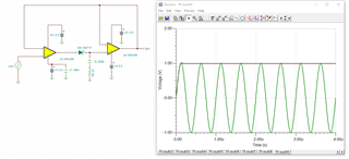
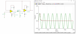
Why does OPA656 behave differently than OPA356?

Thank you.

Regards,

 Vishal

  • It seems like issue is not OPA656. But BAT17 diode rating is the issue. Reverse voltage is 4V. I will have to try with different diode.

  • Hello Vishal,

      Were you able to fix your issue? Yes, but it does look like BAT17 would be the issue due to the higher voltage at the output of the amplifier. You would need to choose a diode with a higher reverse voltage.

    Thank you,
    Sima

  • Hi Sima,

    Thank you for response. I am facing some issue with Tina TI. It gets stuck at start of simulation and is not working. But I had tried using few other diodes yesterday, but OPA656 circuit did not behave same way like OPA357.

    Regards,

     Vishal

  • Hi Sima,

    I changed diode to BAS81. But now Vout droops over the period. 

    I adjusted R & C to 10nF and 3.7ohms. But still output follows input at start and then it droops.


    Regards,

     Vishal

  • You are not inserting the TINA files so hard to know which model rev you are using, 

    You should check the DC input bias current for the two models into the V+ node. 

    Oddly, I went into the OPA656 web folder - not TINA model there anymore - there are of course models around but not sure where you got yours?

  • Hi Michael,

    Tina Version: Version 9.3.200.277 SF-TI

    File atached.

    peak detector circuit.TSC

    Thank you.

    Regards,

     Vishal

  • Well when I bring that file in the negative supplies are not connected and should be -5V on the polarity shown

  • Hi Michael,

    Negative supply is connected. Other one that you have marked, is unused on OPA656. I am swapping amplifier models and some of them have Disable pin. I am using that supply to enable Op-Amp. Example below:

  • I see now, you are correct of course - ok, lets 1st look at the current into the V+ input of the buffer stage (and incidentally, where I am headed is what is the 1st stage output doing after the peak is captured, well, the loop opens and it bangs to the rail - will fix in a bit)

    So probably the diode is seeing that 1V held voltage and big negative voltage as the 1V peak held voltage is on the inverting node and the V+ node falls below that. 

    Yes, coming off the peak, the 1st stage goes to -4V output putting 5V reverse across the diode. 

    I pulled up some older peak detector work, here are those diodes and the catch diode in the input stage, still seeing higher current into the next stage? This is probing current into the V+ of 2nd stage, this current seems high - wonder where it is going? 

    Looking at the input stage output voltage now - you can see the max negative is just about the input swing less a diode = there is a cycle to cycle droop that each pass recharges closer to peak value, 

    And then looking at the final output with the input swing, looks a little better, 

    OPA656 peak detector circuit fixed.TSC

  • Hi Michael,

    Thank you for analysis. We tested OPA357 based circuit with open loop in real set-up and it worked fine. But with 5V Opamp, it makes sense to use closed loop at input stage rather than open loop. Diode selection makes difference though. If I change diode to BAT81, circuit behavior is different.


    Thank you for help.

    Regards,

     Vishal

  • Well it seems to be working now. In the peak detector designs I have done over the years using this topology we often use a different op amp on the input stage. You need the low Ib with speed in the 2nd stage, but maybe not in the first stage where slew rate and high peak output are usually more important than JFET input. That would of course all depend on your signal source. 

    At one time we were actually building this type of circuit in hybrid form for radar channels where I was characterizing capture accuracy with input amplitude and speed. Peak capture will have some error in it that traces back to the the op amp characteristics. 

    I was adjusting your hold cap down to test if it needed to be that large - I think you had that there due to the perceived droop issues - that is of course a tradeoff of initial capture accuracy vs peak to peak droop. 

  • Hi Mike,

    Thanks for detailed explanation. Yes, I started with 220pf cap and increased all the way up to 10nF to tackle droop issue. Thank you for help.

    Regards,

      Vishal