This thread has been locked.

If you have a related question, please click the "Ask a related question" button in the top right corner. The newly created question will be automatically linked to this question.

OPA858: OPA858 Spice model

Part Number: OPA858
Other Parts Discussed in Thread: OPA656

Hello Michael,

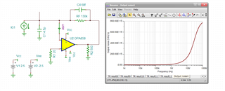
One more question, regarding the Spice model of OPA858.

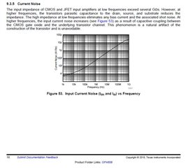
Does it model the effect of noise current increase with frequency, as described in OPA858 data sheet on the page 18?

Thank you

  • Don't know and I had sort of decided this effect is not usually worth considering. It shows up in the designer sims, but if you start trying to make it a dominant term you can't. I tried to measure it a few times on parts like the OPA656 and by the time I got the resistors large enough to gain it up I was bandlimited by their parasitics or their noise dominated. 

  • As I understand it, this effect influencing my decision what opamp to use in TIA, with BJT or with FET input.

    What do you think about the following TIA:

    • OPA858,
    • Cin=4.5pF,
    • Rf=130K, Cf=60fF.

    Simulation shows a bandwidth of 26 MHz, nice phase behaviour, and average RTI noise of about 1 pA/rt(Hz).

    Looking at the graph above, the input current noise should become 1 pA/rt(Hz) at 20 MHz.

    There are two classical sources of noise in this TIA - thermal noise of Rf and e_n of opamp multiplied by average noise gain of the circuit:

    • The 130K resistor makes thermal noise of 0.35pA/rt(Hz)
    • The noise gain is high (1+4.5/0.06=76 at its peak, so 38 in average), e_n*NG_avg=2.5n*38=95nV/rt(Hz) at the TIA output, which gives 0.73pA/rt(Hz) at the TIA input
    • summing both above gives 0.8pA/rt(Hz).

    Simulation shows about 1pA/rt(Hz). Is this because of input current noise rising from the depths, or from other reasons?

    So, will they add, on your opinion, and I should expect to measure more than 1pA/rt(Hz), or the model have this effect inside?

    Could you please, test the model for i_n vs frequency?

    Thank you

  • Looks like it is in the model, just put a current meter into the inverting input and run an output noise sim. 

  • Hello, Michael

    OK, good news. Hope that numerically it is also done correctly.

    Bottom line, it seems to be a very accurate model.

    Thank you very much

    Nice to talk to you, as always :-)

  • Hello Michael,

    One more question regarding OPA858.

    Is it a complete CMOS device (all transistors inside are MOS), or it is a BiCMOS part (most of device is bipolar with MOS/CMOS/JFET input transistors)?

    I need it for thinking about future use of it.

    Thank you

  • With a few exceptions in high speed op amps (OPA3xx series) these CMOS or JFET input devices are complementary bipolar past the input stage - that gives a much higher full power BW/quiescent current ratios.