This thread has been locked.

If you have a related question, please click the "Ask a related question" button in the top right corner. The newly created question will be automatically linked to this question.

AMC1100: Regarding using ferrite bead to reduce switching noise at input of AMC1100 as per suggestion in TIDA-00555

Part Number: AMC1100

Dear TI team,

Good evening.

We are measuring AC voltage of 50KHz switching frequency and fundamental frequency of 50Hz  at input side of AMC1100,which is very noisy.(Kindly find the attached images of waveform.doc)

We are not getting proper AC voltage shape and its flattening, so we assume is it because of gain error?

We wish to reduce 50KHz switching frequency ripples by placing ferrite bead across a resistor as per below image,


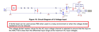
In that case if we place ferrite bead across 332k resistor then net Series resistance also changes.So we need to make changes in Voltage divider circuit to keep input voltage range

with in  +/-250mV range.Right?

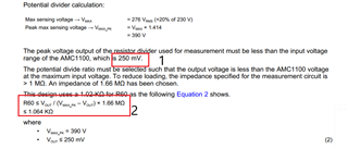
If we place ferrite bead across the resistor,is below calculation still applies?

Thank you,

Girish K

Caliber

6136.Waveforms.docxTIDA-00555.pdf

  • Hi Caliber,

    The input range of the device is 250mV with an internal gain of 8.

    Can you please post the schematic that you are using or confirm if it is the exact same as shown in the TIDA?

    Is the only thing changing between the two waveform captures the sampling mode of the oscilloscope? 

    If so, the bandwidth of the high resolution measurement may not be sufficient to measure the waveform with the switching frequency ripples. 

    What is shown on the output of the AMC1100? 

    When you say placing the ferrite bead across the resistor, do you mean in parallel? 

  • Dear Smith,

    Good morning.

    Thank you very much  for your response.

    May I message you in private message  or mail.

    Kindly accept my friend request.

    Thank you,

    Girish K