A related question is a question created from another question. When the related question is created, it will be automatically linked to the original question.
If you have a related question, please click the "Ask a related question" button in the top right corner. The newly created question will be automatically linked to this question.
AMC1411: how to use AMC1411 to measure -2500V to 3200V?
Part Number: AMC1411 Other Parts Discussed in Thread: AMC3330
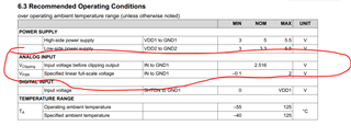
As datasheet shows, AMC1411 support -0.1~2V analog input, input signal range from -2500V to 3200V (AC or DC), how to use AMC1411 to measure -2500V to 3200V?
Out of curiosity, what type of application is this for?
Most often, a resistor divider is used to scale down the high voltage such that it matches the smaller input voltage range, as shown in this cookbook circuit: https://www.ti.com/lit/an/sbaa321/sbaa321.pdf
However, since the voltage to be measured is bipolar and the input voltage range of the AMC1411 is unipolar, this poses an extra challenge that may require additional circuitry, such as a 1V DAC and amplifier, to allow the bipolar sensing voltage to swing +/-1V within the 0-2V input range of the AMC1411. An example of a possible implementation is shown in this thread: https://e2e.ti.com/support/amplifiers-group/amplifiers/f/amplifiers-forum/986917/amc1311-sch-for-amc1311
Also as mentioned in the thread, the AMC3330 has an input voltage range that is ideal for this type of application, +/-1V. This device includes an integrated DC/DC converter which greatly simplifies the high side supply design. However the isolation ratings of the AMC3330 are lower compared to the AMC1411 and may not meet the customers requirement.
I can understand your suggestion, so I decide to scale down input voltage range to ±1V, and add a 1V reference voltage to shift the input range up to 0~2v.
As the primary side is high voltage side, and the the reference voltage IC at this side.
My last question is that should we consider the high voltage risk( or withstand voltage parameter) for reference voltage IC ?
The reference IC should output 1V with respect to the high side ground, GND1, so it should be powered from the same high side voltage rail as the AMC1411 VDD1. There are two options here:
1. The reference IC can be a non isolated component, such as an OPAMP and float on the high side where the withstand voltage parameter would not be applicable.
2. The reference IC could also be an isolated component, controlled from the low side, which would require considering the withstand voltage parameter determined by the isolation requirement of the application.
The reference IC may need diodes, current limiting resistors, or some other type of protection if high voltage/current transients are expected.
Please let me know if you have additional questions.
If the shift voltage is fixed 1V and for the purpose of improving measurement accuracy, Which solution is better compared to reference voltage IC and DAC + buffer?
Of course there will be some variation in accuracy between the two solutions with changes in price. In general, I would expect a reference voltage IC to have higher accuracy, but also a higher cost. A buffer will have inherent offset that would contribute to the error. The customer may want to consider doing an offset calibration at start-up to keep costs low and accuracy high.