This thread has been locked.

If you have a related question, please click the "Ask a related question" button in the top right corner. The newly created question will be automatically linked to this question.

OPA3S2859-EP: OPA3S2859-EP

Part Number: OPA3S2859-EP

Hi,
I just got a new board with OPA3S2859-EP. I do not see output on VOUT_A p19 when I put 20mV from 50 Ohm signal generator at 500 kHz
I use single pole power supply of 5V. INA+  and INB+ connected to 2.5V with bypass cap.
There is not much to configure for this OpAmp and here is what I have
Pin Voltage
1………..2.5V
2…………5V
3………….5V
4…………...5V
5……………5V
6…………….2.5V
7…………….N/C
8……………..N/c
9……………...100k resistor
10…………….10k resistor
11……………..1k resistor
12………………100k,10k,1k combined
13……………..GND
14………………5V
15……………….5V
16……………….5V
17………………..5V
18………………..GND
19………………..100k,10k,1k combined
20………………..1k resistor
21………………….10k resistor
22………………….100k resistor
23…………………..50 Ohm signal generator 20mVp-p
24...........................N/C
When I look at p19 Vout_A I see DC at 4.5V, at p24 IN_A- I measure 2.1V dc. This is a new chip and the data sheet does not provide single pole power supply schematics.

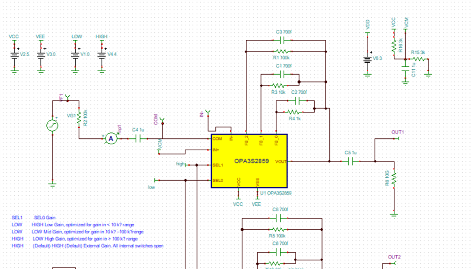
I did run simulation which showed me it should work in this configuration It draws 50 mA at 5V

Thanks vadim

  • One more thing, If I add to my 50 Ohm sig gen 10k series resistor, apply 1 V from sig gen and measure voltage at the sig gen end of resistor and op amp input  the voltage does not change much. I would expect the input voltage to be very low. 

  • Hi Vadim,

    The input is designed to be a current source input from a photodiode. When you test it using a voltage input, it is very easy to drive the output into one of the rails. Since Vin-=2.1V < Vin+=2.5V, and Vout= maxVout= 4.5V, it sounds like the amplifier output is simply out of range.

    Can you offset your voltage signal to have a 2.5Vdc average? This will make sure that the the output is also at 2.5V (mid-supply) on average, and can swing up or down. In addition, with 10k as a series source resistor and 100k as a feedback resistor, the amplifier will have an inverting voltage gain of -10V/V, so make sure to keep the input voltage amplitude below: 1.5V(distance to the rail) /10(inverting gain) /2(since the signal generator doubles the voltage to account for 50 ohm impedance matching, unless using high-Z mode) = or less than +/-75mV. It sounds like both of your select pins are high (11), but the VinA- is floating? If so, you should enable one of the channels (00, 01, 10) if there is no external feedback path.

    Best regards,

    Sean

  • Hi Sean,

    Thanks for your support! My sig gen is AC coupled. So I have input properly centered around Vin+ (2.5V). When I use series resistor 10k in series with sig gen output I think this is a good approximation for current source. The input impedance for TIA should me much lower. From simulation it seems to be around 60 Ohm. 

    "It sounds like both of your select pins are high (11), but the VinA- is floating? If so, you should enable one of the channels (00, 01, 10) if there is no external feedback path."  I have this schematic , that seems to work fine. I presume 00, 01, 10 means inputs to SEL1, SEL0? If I look with the scope I do not see much voltage drop across R2. In the simulation it drops from 1V to 10 mVp-p. Thanks Vadim

  • Hi Sean,

    I did not realized 11 does not enable any channel, If I go to a different combination I do see output.

    thanks vadim