This thread has been locked.

If you have a related question, please click the "Ask a related question" button in the top right corner. The newly created question will be automatically linked to this question.

INA181: INA181 failing - why?

Part Number: INA181
Other Parts Discussed in Thread: LM358, TINA-TI, INA381

I have had several INA181 parts die on me where the output goes to VS (which is 3.3V).  I'm sensing current in my 12 V line, and at times I have a INA181 that just dies.  Would it fail if I had 12V at my sense resistor but my Vs was not applied yet?  Or, if the Vs voltage was turned off before the 12V at my sense resistor?

  • Eddie,

    Welcome to the TI forums!

    Power sequencing should not be causing issues on the INA181 (we state in section 10 of the DS "The INAx181 also withstand the full differential input signal range up to 26 V at the IN+ and IN– input pins, regardless of whether or not the device has power applied at the VS pin"). When you say the units "die," are they simply latching up (i.e., power cycling resets them to working order) or do they need to be replaced once the event occurs?

    Would it be possible to see a schematic here? Also, can you describe the nature of the signal you're measuring on the sense lines? 

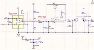
  • Thank you for your response!  Below you will see a schematic.  The sense pins are tied to either side of a resistor on the 12V power coming into the circuit.  It is set to measure 120 Amps or so, and we are having trouble at currents below 8 Amps (haven't gone higher yet).  I think one problem was that your OpAmp has 12V power it and so the feedback was most likely over voltage at  pin 1 of the INA181.  We dropped that 12V at the OpAmp to 5V, but had one more failure.  The failures cause the voltage at pin 1 to go to VS.  I ohm very low ohms at pin 6 to pin 2, but the interesting thing is when I have voltage applied there is 3.3V at pin 6 (not shorted).

  • Eddie, 

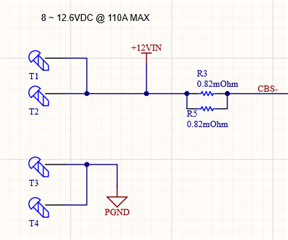
    A few additional questions here: how is the CBS- node referenced to PGND? Is it possible to see the shunt side of the schematic? What value are you feeding to "EN," i.e., what is the magnitude of Vs here, 5V?

  • You bet.  I've attached that portion of the schematic below.  It is 12 Vdc to PGND.

  • Eddie,

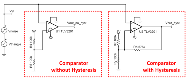
    Looking at this a bit more, it finally clicked that there's positive feedback here. Are you trying to set up the LM358 as a comparator with hysteresis? I think you were on to it with your initial assessment. If this is the case, the reference is typically fed to the IN+ terminal and then the drive signal sent to the IN-:

    I believe it may just be that your terminals are flipped heading into the LM358, and with them flipped, when you're placing the drive signal on IN+, you enter a positive feedback loop that is leading to the lockup of the system. You may also just be shot to the rail because the inversion would be triggering the comparator at all points in time. Please let me know if this is what you were trying to do with the LM358 and your thoughts. 

  • Yes you are correct, I was trying to use this as a comparator with hysteresis.  This part is lower cost than the comparators that we use;)  So, yes I think the feedback of near 12V was damaging the INA181 output.  But I did have one more failure even after I changed the 12V to 5V.  Maybe it was a fluke, or is there possibly anything else?

  • Eddie,

    I'm a bit confused by this statement so I just want to verify: when you say you "changed the 12V to 5V," are you saying you changed the V+ pin of LM358 to 5V from 12V, or something different?

    As I mentioned above, I would actually switch the terminal insertion points of the INA181 and the reference such that the reference enters the positive node and the output of the INA181 enters the negative terminal as shown in the image above. This should ensure proper orientation of the inputs into the comparator and that no instability situations occur. 

  • Thanks Carolus for your fast response!

    Yes, I changed the V+ to the OpAmp to 5V from 12V, so that the 12V feedback will not overvoltage the INA181.  With the reference tied to the (-) pin it insures the output of the OpAmp is also negative as power comes up.  This keeps the transistor OFF.  We want the transistor to turn on when the current at the current sense is high enough to bring the output of the INA181 high enough (above the ref voltage) at the (+) pin of the OpAmp to cause the output to go high which will turn on the transistor and provide hysteresis at the (+) input.

    Does that makes sense?  Do you see a chance for instability?  If there is instability, can you see that damaging the INA181?

    Thanks,

    Eddie

  • Eddie, 

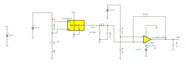
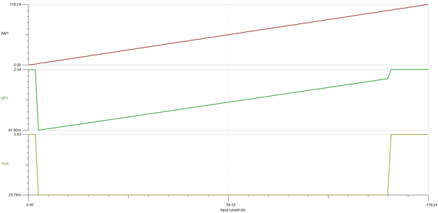
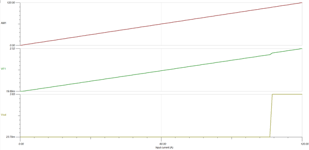
    I ran some quick sims of this setup, and it does look like some wonky stuff is happening when the LM358 is run from 12V: 

    Its not showing it at 8A in sim, but notice the instability at lower voltages. This seems to rectify itself when the devices are powered by a similar supply voltage: 

    If 12V were to make it to the output pin of the INA181, the device would certainly become damaged. From the abs max table of the datasheet, the output pin of the device can only tolerate being raised about 300mV above the supply of the device:

    INA181 LM358 Comparator with Hysteresis.TSC

  • Thanks Carolus,

    So, do you see any problems that might occur if both are run off of a 5V power?  The Ref probably should be run off the same power as well.  Right now it is running off of the 12V input.  Do you see any potential problems that might have occurred because of the 12 V being there before the 5 V, or after (they were probably applied at different sequences in the lab).  Also, the 100k ohm resistor was  not installed.  Do you see a potential issue with this?

    Moving ahead, would you recommend using and actual comparator instead of the OpAmp?  Are there suggestions for making this circuit more robust that you might suggest?

    BTW, are you using TINA?

    Thanks,

    Eddie

  • Eddie,

    I think 5V power to both devices should alleviate the issues you were seeing, and yes, if the 12V power rail was brought up prior to the INA181, that would certainly have the potential to cause issues. If the circuit can be run from 5V I would recommend it, but also note that the LM358 is not a rail to rail device, and will only swing up to V+-~1.5V according to its datasheet. 

    Regarding your simulation question, yes the simulations above were performed in TINA-TI. I attached the sim to the prior post if you'd like to have a look.

    If you look to move to an actual comparator solution, have you considered the INA381? This would provide an all in one low-cost solution if you can work with a built-in 50mV hysteresis. 

  • Carolus,

    Thanks for the great feedback!  Have you found that the INA181 or others in the series are at times damaged by transients at the input, or with the resistor divider inputs, are they pretty robust?  Is it recommended to place RCs at each input for some protection?

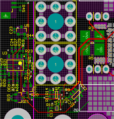
    Would you mind commenting on our placement of the current sense to the INA181?

  • Eddie,

    The inputs should be fine provided the abs max conditions are not violated. Resistors can theoretically be placed in line for additional protection, but we typically advise against additional resistance on the line due to the gain error these will add to the system (this is covered in section 9.1.3 of the DS).

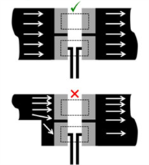
     Th current traces are a bit long, but they are matched so should be fine. You may wish to move the tap point down a bit so it internal to only one of the resistors. You should also ensure that the track for the current flow across the parallel resistors is as even as possible for optimal results. 

  • Thank you for all your help on this!  You've been great!