This thread has been locked.

If you have a related question, please click the "Ask a related question" button in the top right corner. The newly created question will be automatically linked to this question.

OPA855: How to design a TIA with OPA855?

Part Number: OPA855
Other Parts Discussed in Thread: OPA859, TINA-TI

Hi,I'm designing a TIA with OPA855.

However, there is no output.

Would you please give me a hand?

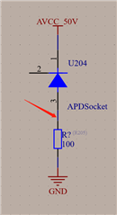
The schematic is attached as below. Just measure the output(RED ARROW) and get almost constant 1V.

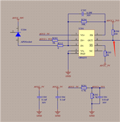
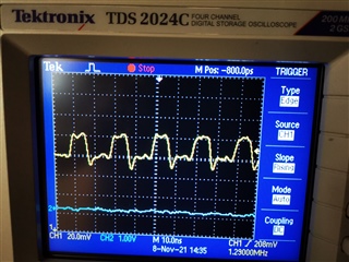
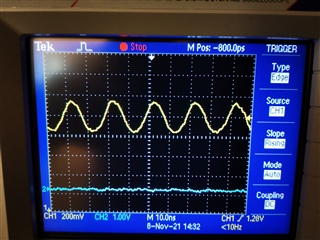
I have measured the signal(RED ARROW) as below and get 50MHz waveform,whose Vpp is almost 5mv.

  • The parameters of this APD is listed as below.

  • Hello,

      I can't see anything wrong with your schematic. Even if there is no input, you should still see about 2.5ishV DC at the output. But, that was a good test with the shunt resistor and photodiode. How much current is being supplied to the amplifier, should be around 18mA. Is the photodiode internal capacitance in the last column (0.280pF?)

    Thank you,

    Sima

  • Yes, I can get 2.5VDC at the output. However, there is no waveform at the output.

    The current supplied to the amplifier is OK.

    The photodiode internal capacitance is 0.28pF, or 280fF.

    Why there is no waveform at the output?

  • I just change the position of the APD.

    The waveform of the APD( The second red arrow listed as above) is listed as below.

    The waveform of the TIA(The first red arrow listed as above)is listed as below.

    It seems that the high frequency part is filtered.

    Is there anyway to solve it?

  • Hello,

      Thank you for the additional scope shots. That is a very small input capacitance, can you remove the feedback capacitor. The parasitic from the board should be enough in this case to stabilize the amplifier.

      For this type of application, I wouldn't recommend the OPA855. A 50MHz signal, 30kOhm gain, and very small input capacitance, you would only need an amplifier with about 40-100MHz gain bandwidth. Also, would recommend a FET input which will give a very low bias current and avoid a large offset at the output of the amplifier. In this case, with about a 5u input current, the output should be around 150mVpp. A 12u input bias current from the OPA855 would give around 350mVpp if not properly matched at the non-inverting input of the amplifier. 

     We would suggest the OPA859. The OPA859 is a p2p (same package and pin layout) replacement of the OPA855. Tina-TI simulation of your schematic with OPA859 is attached below. 

    OPA859_TIA.tsc

    Thank you,

    Sima