This thread has been locked.

If you have a related question, please click the "Ask a related question" button in the top right corner. The newly created question will be automatically linked to this question.

LM6211: Bandpass Filter

Part Number: LM6211
Other Parts Discussed in Thread: OPA810

Hello, 

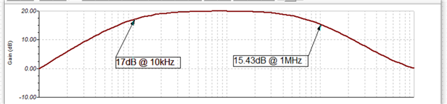
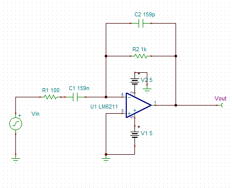
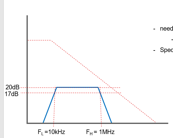
I am designing a bandpass filter with a 20dB gain between 10kHz and 1MHz.The Input signal swing is +/- 10mVpp and the desired output swing +/-100mVpp.

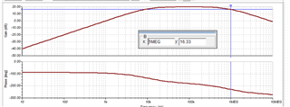
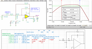
Below is my TINA simulation of the BP filter I designed. I am not sure where my component selection went wrong.

Why is the gain response 15.43dB at 1MHz? This gain should be 17dB at 1MHz.  Do I need to recalculate my C2 value? 

CS3 - LM6211 - Bandpass.TSC

Best regards,

Lucas Pucheta

  • Hello Lucas,

    An Ideal amplifier would be 17dB at 1MHz.

    The circuit has a noise gain of 11 (1000/100+1) and GBWP of op amp is 20MHz.  20MHz / 11 = 1.8MHz, that is not a lot of margin over 1MHz. The op amp's GBWP is another LPF so that accounts for the 1.6dB extra loss.

    You can adjust C2 to compensate. For a more reliable upper cutoff, try a faster op amp.

  • Hello Ron,

    I took your advice and choose a faster op amp (OPA810). However, I still do not get 17dB at 1MHz. Is 16.33 close enough or is it possible to compensate C2 to get 17dB at 1MHz. 

    I used the following equations to find the component sizes. How would I approach adjusting C2 to compensate for this loss of gain. 

    Choosing R2 = 1KΩ  

    -R2/R1 = 10v/v R1 = 100Ω

    1/(2∗pi∗(100)∗C1) = 10kHz ∴ C1 = 159nF

    1/(2∗pi∗(1k)∗C2) = 1MHz ∴ C2 = 1.59E-10 = 159pF

    Best regards,

    Lucas Pucheta

    CS3 - OPA810 - Bandpass.TSC

  • Lucas,

    16.34dB/17dB =  92.7% , yes that close enough in a log world. Or another view, 17dB at 867.2kHz , 86.7% of 1MHz

    159pF * 86.7% = 138pF and that gives sim result of 16.91dB at 1MHz. Or doing trial and error to get 135pF = 16.99dB

    Capacitor's capacitance are not that accurate anyway. Is there a reason to get "exact" upper and low cutoffs or is this just a knowledge quest?

  • This is just a knowledge quest and I appreciate your guidance!!

  • Morning Lucas, 

    To continue on this a bit, often for these broadband BP designs we do a 2nd order MFB LP with an AC coupled input. 

    1MHz butterworth 2nd order with gain of 10 is actually quite high, the OPA810 is marginal on GBP margin but can be designed with RC adjustment flows for the relatively low minimum loop gain inside the filter (essentiallyw what Ron is saying about low GBP). Doing that design, then adding a 1st order HP as the input R is just the 1st resistor in the MFB, gives this design hitting things very accurately - in active filter design, I use 2% C0G SMD C's and 0.5% R's to get better spread, these have come way down in price, 

    the min loop gain thing inside the MFB is where the low GBP errors come in, that is shown here for this design where that <20dB min values is lower than I would normally do, (the OPA810 TINA model has a GBP = 63MHz). 

    And this file 

    OPA810 BP filter with 2nd order MFB.TSC