This thread has been locked.

If you have a related question, please click the "Ask a related question" button in the top right corner. The newly created question will be automatically linked to this question.

PGA308: Vout is outputting -135mV regardless of RAM values

Part Number: PGA308

Hi there,

I am using the TI USB DAQ and PGA308EVM software to program our PGA308 on our own PCBA. I am able to program our PGA308 using the GUI and verify that the RAM values change but the Vout values remain negative regardless of the gains.

The input to Vdiff of Vin 1 and Vin 2 is roughly 0.4mV.

I believe the PGA308 should not be able to output negative voltages, is that correct?

  • HI Kanisius,

    The PGA308 output swing is delimited by the device supplies.  The output swing limit depends on the current load conditions, for example, it is specifies to 100mV above GND, and VS-100mV, while driving a 4mA load (unless limited by the over/under-scale setting or the VCLAMP pin).  On the PGA308EVM on the default configuration, the device is powered by a unipolar supply with Vs=5V, GND=0V; therefore the device can not output a negative voltage with respect to its ground pin.

    Since this issue is occurring on a Custom PCB board, please provide the following information:

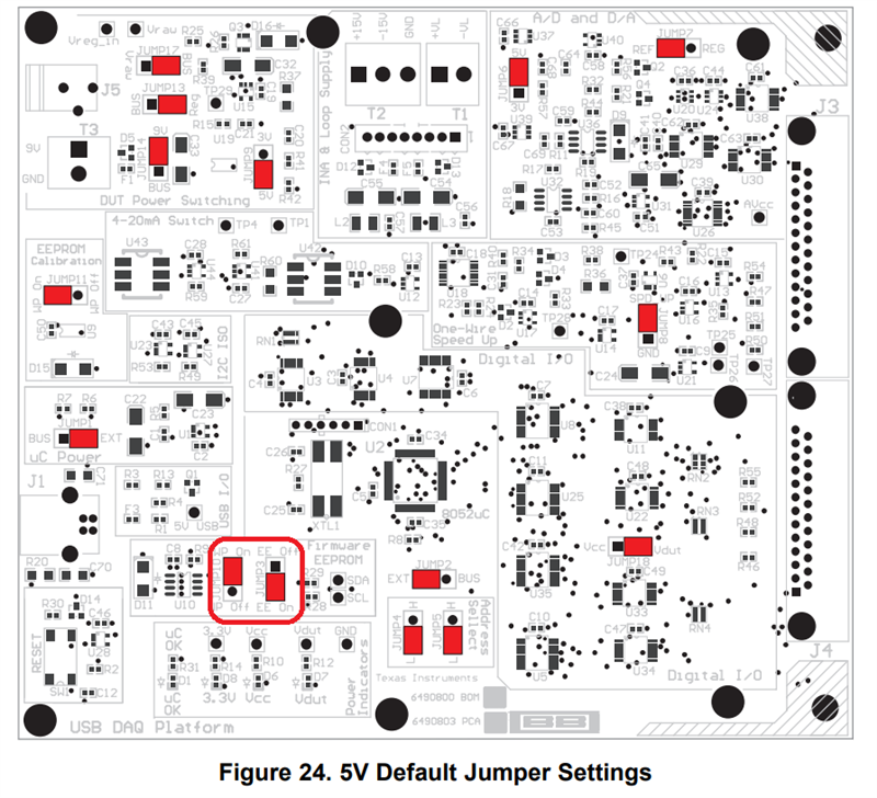
    1)  Please provide a complete schematic of your PCBA board.  Please also include a diagram showing all the connections between your PCBA board and the USB-DAQ.  Please confirm the USB -DAQ jumpers are configured as shown on the figure below.

    2) Clarify if you are using an external sensor to produce the input voltage or the USB-DAQ sensor emulator circuit. If using the external sensor, please show all your sensor connections including excitation, sensor GND  connections and signal connections to the PGA308 inputs.  If using the USB-DAQ sensor emulator, show the sensor emulator circuit on your PCBA and the connections between the custom PCBA PGA308 inputs and the USB-DAQ.

    3) Are you measuring Vout with external meter, measuring the Vout and GND pins of the device or are you using the GUI in the "Block Diagram"?  If you are not using an external meter, please measure the voltage right at the Vout pin of the PGA308 with an external meter.   Ensure to refer the voltage meter measurement to the PGA308 GND pin and confirm the PGA308 output voltage.

    4) What is the common-mode voltage of the input differential signal 0.4V with respect to the PGA308 GND pin?  Can you verify with an external meter the VCM voltage with respect to the PGA308 GND and the Vdif voltage across the inputs of the PGA308 using an external meter? 

    5) Please let me know in detail the Registers Settings you are programming, and if you intend to use an output voltage module on 4-wire or 3-wire configuration; or if this is a current output module.  Clarify the PGA308 settings you intend to use:  Front End Gain, Output Amp Gain, Coarse and Fine offset, GDAC Fine Gain settings, overscale settings, etc.

    Thank you and Regards,

    Luis

  • HI Kanisius,

    I am assuming the issue was resolved, and I will close this thread.  However, please feel free to post if you have questions.

    Thank you and Regards,

    Luis