This thread has been locked.

If you have a related question, please click the "Ask a related question" button in the top right corner. The newly created question will be automatically linked to this question.

OPA2192-Q1: current measurement for Moto application

Part Number: OPA2192-Q1
Other Parts Discussed in Thread: OPA2192, OPA388

Dear expert,

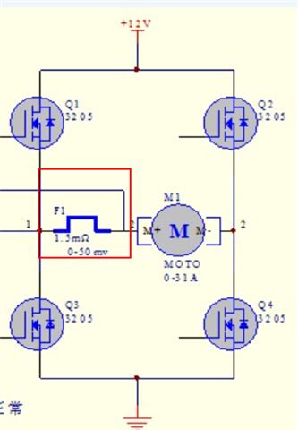
I want take measurement for current flow through Moto with OPA2192.

1.5mohm current sensor resistor is in below position. 

The challenge is the current flow in both direction. 

In one direction, voltage is 12V to 12V-50mV cross current sensor resistor.

In another direction, voltage is 0V to 50mV cross current sensor resistor.

How to amplifier this signal with OPA2192 and then send to ADC inside MCU?

Great thanks 

  • Hi Ryan,

    The first concern here is that this looks like a full-bridge, meaning that the common mode signal will swing from the positive rail to GND.  Let me first answer the bi-directional circuit, then I'll talk about the issues with the common-mode swing.

    To achieve bidirectional current shunt monitoring, the output "zero" scale signal has to be shifted so the output can swing either positive or negative relative to what the "zero" voltage is.  An example is seen below, this is in many of our data sheets, below was taken from OPA388:

    In this example, a dual amplifier is used.  The amplifier on the bottom is configured as a differential amplifier with the output referenced to Vref.  When the voltage across RSHUNT is zero, the output voltage will sit at VREF.  The output will swing around VREF according to the voltage across RSHUNT gain of the diff. amp (if R1=R3 and R2=R4, then Gain = R2/R1).

    The input also needs to be within the input common mode range, but, since the output and VREF voltage are shifted positive, this is generally not a limitation with amplifiers that swing to the negative rail.

    Now, regarding common-mode swing, consider the circuit below, connected in the bi-directional current sensing scheme:

    Here, the differential gain is 50, the input signal is represented by a DC voltage source V2, the output is shifted by 1 V, shown by V1, and the differential output voltage is measured by VM1.  The signal generator "Vin" represents the common mode voltage between Q1 and Q3.

    The response of the differential output voltage, VM1, along with Vin, is plotted below:

    Note that the output signal will require settling time after each switching event; the settling time is a factor of the slew rate of the amplifier and the gain/feedback configuration.  If the switching is too fast, then the output may never give an accurate representation of the shunt resistor voltage.

    What is the switching frequency of the bridge you are showing above?

    Best Regards, 
    Mike

  • Mike,

    Great thanks for your detailed explanation. This help me a lot.

    Switching frequency is 20KHz. This should be not a challenge for OPA2192, right? 

  • Hi Ryan,

    This should be not a challenge for OPA2192, right? 

    Yes, this is correct. OPA2192 has a BW of approx. 10MHz. It should not be an issue. 

    BTW, you may also consider to use our instrumentation amplifier or current monitor for the current sensing application. I think that the switching voltage spikes will be high across the sensing resistor from the motor load, which is driving in square wave (and in high current). You may consider to place protection circuitry to guard against overvoltage in transient events, inductive kickback from the motor. And the current sensing circuit will require excellent CMRR at the switching frequency to reject the common mode noises. 

    Best,

    Raymond

  • Raymond, Mike,

    Great thanks for your help.