This thread has been locked.

If you have a related question, please click the "Ask a related question" button in the top right corner. The newly created question will be automatically linked to this question.

THS3491: Max output current

Part Number: THS3491

Hi,

I would like to ask you a few questions about the "continuous output current" of  "Absolute Max Ratings".

There describes the data is "+/100mA" (datasheet page5, 7.1).

Q1) Will you tell me the meanning of "long-term"?

       And about +/-100mA, is this vallue "RMS" or "Peak" ??

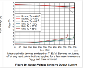
Q2) On the other hand, there describes "Ioutmax" value (520mA typ) on the datasheet page 7.

       What is the difference between "Absolute Max Rating" and "Ioutmax"?

Q3) What is "Iout linear" (datasheet page 7)?

       What is the difference between "Ioutmax" and "Iout linear" ?

Q4) I have tried to drive 16Vpp/50ohm (= 320mApp) @12.88MHz. (Vs=+/\10V)

       I think that THS3491 can drive this current but I am concerned with the "Absolute Max Ratings" +/-100mA.

Thank you for your support.

Best Regards,

Takumi

  • Morning Takumi-san,

    Yes there are quite a few different output currents specified here. 

    In the ABSMAX table, that is a continuous RMS current that can be supported with no metal migration issues. And long term is >years

    Then in the parametric tables

    The Ioutmax is is a tested parameter with a higher output voltage - I think maybe looking at an error from the expected output voltage - kind of making sure the short circuit protect has not kicked in where it is coming in at about 620mA nominal

    The Ioutline is a lower test current where the internal open loop transimpedance gain is re-tested to confirm the device still has a lot of loop gain under those conditions for linear operation

    Your 320mA should be easily supported for linear operation - that does exceed the 100mA continuous RMS in ABSMAX table, but presumeably your application might power down at some interval? However you are using 10V supplies? that is only 2V headroom for an 8V output swing. This is the claw curve of headroom vs output current. The +/-7.5V table has more resolution, the no load headroom varies from 1.5V up to 1.7V and this curve shows another say 0.4V IR drop at 300mA for a maximum 2.1V headroom over process and temp. That is getting into clipping possibly and then if you tolerance your +/10V supplies a certain risk. Perhaps you need to increase your supplies to maintain a for sure 2.2V headroom over supply tolerancing. 

  • Hi Michael-san,

    Thank you very much for your kind reply !

    I understood well and I will reconsider my design.

    Best Regards,

    Takumi