This thread has been locked.

If you have a related question, please click the "Ask a related question" button in the top right corner. The newly created question will be automatically linked to this question.

TL082-Q1: the difference between TL082-Q1 and LM358B

Part Number: TL082-Q1
Other Parts Discussed in Thread: LM358B

Hi all,

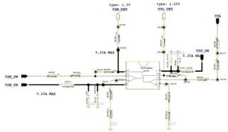
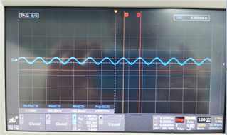
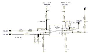
My customer is experiencing an issue where the oscilloscope test on the -VIN end of TL082-Q1 has an interfering waveform, the -VIN end test on the LM358B does not, and the solution is to test the oscilloscope in series with a large resistor, what is the reason for this?

  • Hi Hazel,

    This sounds like it might be a stability issue but I'll need more information to confirm. Can you share the op-amp schematic? 

    Thank you,

    Robert Clifton 

  • Robert,

    Please see the attachment. The customer is switching between TL082-Q1 and LM3558B.

    The possibility is due to the different production processes of the two. TL082-Q1 is FET and  LM3558B is BJT. The TL082-Q1 has a higher input impedance and is more susceptible to interference?

    The customer’s function with this AMP is to reduce the voltage in reverse proportion, Based on this application, will the input side need  more resistant to interference?


  • Hey Hazel,

    Could you please include a higher resolution photograph of the schematic? I am unable to read any of the component values.

    Best,
    Jerry

  • Hi Hazel,

    I have a few follow-up questions:

    - It looks like both channels are very similar but with different resistances on only the positive inputs. I presume they see this issue on both channels?

    - What is the voltage of VSN_SW, VSP_SW, and VGL? 

    - I'm assuming VSW_DET = 1.3V and VGL_DET = 1.66V? 

    I'm wondering if the capacitance introduced by the inclusion of the oscilloscope probe is causing instability to the system. Have you noticed a performance difference in the system when you have the oscilloscope probe on -VIN versus when there's no probe? 

    Best Regards, 

    Robert Clifton 

  • Hi Robert,

    -Only TL082-Q1 has this issue.

    -VSN_SW=-6.5V,  VSP_SW=6.5V, VGL=-10V

    -Yes,  VSW_DET = 1.3V and VGL_DET = 1.66V

    -It seems the capacitance introduced by the inclusion of the oscilloscope probe is causing instability to the system, When a large resistor is connected in series between the probe and the test point, the issue disappears

    My puzzling point is, if the test abnormality is due to the manufacturing process, does that mean FETs are more susceptible to interference, and we recommend customers to use BJT more?

    thanks 

  • Hi Hazel,

    I should have been more clear with my first point. I meant to ask are both channels of the TL082-Q1 having this issue? 

    My puzzling point is, if the test abnormality is due to the manufacturing process, does that mean FETs are more susceptible to interference, and we recommend customers to use BJT more?

    Not necessarily. Op-amps are designed for different purposes. Factors like bandwidth, output current, etc, change stability of one op-amp from another. That's why it's important to run stability analysis on circuits! 

    Does the customer have a low capacitance probe that they could use to verify if it is indeed the probe that's causing this oscillation? 

    Best Regards,

    Robert Clifton 

  • Hi Robert,

    Both channels of the TL082-Q1 have this issue.

    Does the customer have a low capacitance probe that they could use to verify if it is indeed the probe that's causing this oscillation? 

    No, after the resistor solved the problem, they would be more interested in knowing the cause and the type of choice that followed.

  • Hi Hazel,

    If it is indeed the probe's capacitance that is causing this oscillations then the customer's next option is to determine if they can continue using the TL082-Q1 knowing this. 

    Best Regards,

    Robert Clifton