This thread has been locked.

If you have a related question, please click the "Ask a related question" button in the top right corner. The newly created question will be automatically linked to this question.

INA280: Location of INA280 when operating with TPS2660

Part Number: INA280
Other Parts Discussed in Thread: TPS2660, INA303, INA302, INA301, INA381

Support Team,

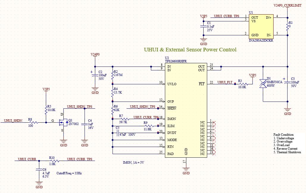
Below is our current configuration of the design. Since TPS2660 current measurement has 8.5% tolerance we are planning to implement INA280 externally. Can you please let me know what will be the best location for INA280? Will it be at output of TPS2660 or at input of TPS2660. The reason i am asking as when TPS2660 is off, Pin 5 of INA280 will be floating. Just checking for safe operation,

Please ignore the value of R1 as is shown just for reference. As per our calculation for current, we will be using 50mOhm.

Looking forward to hearing from you soon.

Thanks.

  • Hi,

    Since the INA280 output is being used for current limiting which is a critical function for the circuit, it is probably a good idea for it to be able to provide deterministic values under all circumstances, including when the TPS is off.

    This means we probably don’t want INA280 input to be floating at any time. To avoid the situation, moving it upstream of the TPS is one option as you mentioned. The other would be to have a dummy load downstream. This could be a resistive load you may already have.

    Just a note that the INA280 inputs may need to be swapped. Otherwise its output is going to be stuck at ground. Further the schematic shows the output pin is connected to the IMON pin directly, which is probably OK, but the IMON output is going to be overridden.

    In case an integrated comparator makes the design easier, we do offer this type of current sense amplifiers. Examples are INA381, INA301, INA302 and INA303 just to name a few.

    Regards, Guang