This thread has been locked.

If you have a related question, please click the "Ask a related question" button in the top right corner. The newly created question will be automatically linked to this question.

LMV321-N-Q1: temp influence

Part Number: LMV321-N-Q1
Other Parts Discussed in Thread: LMV321, ADS7052

Hi Team,

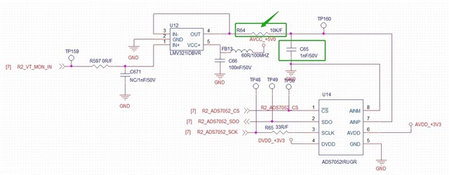
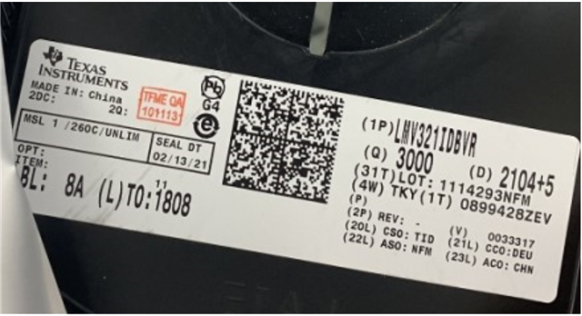
LMV321IDBVR is used in the voltage monitoring circuit, customer encountered a problem in the test:
When testing at low temperature of -40 degrees, the monitored voltage value is too high (for example, the actual voltage is 8V, and the voltage is estimated to be about 9V based on the monitored voltage),
Preliminary analysis determines that the cause of the problem is related to the chip LMV321, please help with further analysis.

Describe the problem again:
The ambient temperature is -40 degrees Celsius. It is OK at room temperature 25 degrees and low temperature -30 degrees. The monitored voltage is too high and does not change linearly with the decrease of temperature.
But when the temperature drops to a certain level (about -40 degrees), the monitored voltage suddenly becomes higher.

  • Hello Amelie,

    The complaint is super vague. So I have to take a guess. Check the op amp input voltage input relative to V+ supply voltage. LMV321 is not rail to rail input. The colder the op amp becomes the more limited the VCM will be. 

  • Hi Ron,

    Thanks for your reply. I am checking with customer about the input.

    Just attached the SCH here. Could you help to check whether the SCH is ok?

    It is normal during -30℃ to 25℃, only abnormal in -40℃.The monitored voltage does not change linearly with the decrease of temperature, but when the temperature drops to a certain level (about -40 degrees), the monitored voltage suddenly increases.

    During -40℃, it is abnormal:

    1. The signal skips U12,(disconnect R597 and R64, flying wire from TP159 to TP160), the test is ok.

    2.The C65 value has been adjusted, but the problem cannot be solved.

    3. Adjust the resistance of R64: 0R test is OK; the larger the resistance of R64, the higher the voltage.

    4. Replace with a new U12, test OK. But replace the old U12 to test again, there are still problems.

  • Hi Ron,

    Just got customer feedback.

    VCC+ is 5V and input range is 0.27-2.9V. It is not too large...

  • Amelie,

    Can you provide a table of VIN and VOUT when the issue is present. I'd like to know how high is the output and the relationship between input and output. How many units have this issue? Is this a new or existing design? 

    Because the changing R64 made a difference, check the output pin for oscillation.

  • Hi Ron,

    1. A total of 45 units were tested, and 8 of them were abnormal.
    2. As mentioned in the previous, the high voltage is related to the resistance of R64: customer adjust the resistance of R64: 0R test OK; the larger the resistance of R64, the higher the voltage.
    But replacing LMV321IDBVR is OK.
    Customer have verified that R64=0R is OK, so at this time it is equivalent to testing the output pin of 321.

    In addition, customer have also tried to change the power supply voltage of LMV321 to 3.3V, which is OK, could you kindly help to analyze this?

    At least, customer would like to see whether their SCH is ok or not?

  • Amelie,

    I could help better if I had the data I requested earlier. Keep in mind that LMV321 is not rail to rail input; if input range is violated then output may limited to around 4.3V or may jump to 5V. The same thing would happen at a lower voltage if 3.3V was used.

  • Hi Ron,

    Here are the test point customer test. When in high or room temperature, the output is very stable.

    But when change to -40℃, it is abnormal. The output is not only higher but also unstable,  (the fluctuation range is about 0.1V). When change to other chip LMV321, it could work.

    Any other advice? whether you meet such an issue? We are very worried about consistency


    Vin

    Vout


    Temp=25

     0.51V

     0.51V

     0.96V

     0.96V


    Temp=-40

     0.51V

     0.64V

     0.96V

     1.088V


  • Amelie,

    Thank you for the data, this is very helpful. I believe the output has an oscillation induced by system noise in ground or VCC+.

    I can verify this theory if a had a waveform of the oscillation on op amp pin 4. I expect a short pulse repeating at a frequency near 9 MHz.

    The op amp is most sensitive to supply noise when temperature is lowest and VCC is highest. 

    What is the occurrence rate of this issue?  [No good] / [total built]

    Part is the full part number and reel lot information?

  • Hi Ron,

    It is hard to measure the waveform of pin4.

    The sampling voltage of the LMV321 front stage is gated and connected by the analog switches of 30 channels. And customer got the output voltage through reading register. 

    When the oscilloscope probe is connected to Pin4, and the system will read the value of register automatically. The output is normal when reading the register. Therefore, it is not feasible to check whether the output waveform is OK by connecting the oscilloscope.

    Customer suspected the possibility of OP output oscillating, so they tried to put a 1k resistor in series in the feedback loop, but the output voltage did not improve significantly.

    Any other advice? Customer now found one fail even in -10 ℃, and customer strongly ask us to do FA through our CQE. What do you think about FA, does it make sense?

    What is the occurrence rate of this issue?  [8] / [45]

  • Hi Ron,

    The log is as following:

  • Hi Amelie,

    are you sure the LMV321 is fast enough to drive the ADS7052 properly? The datasheet of ADS7052 shows a 200MHz OPAmp at the input of ADS7052:

    Also, R64 must be chosen very carefully to not only keep the driving OPAmp stable but to also allow the charge bucket filter cap to be charged fast enough. So R64=0R and R64=1k might not be good choices.

    That the LMV321 seems to work at room temeprature but not at very low temperatures, might mean that the LMV321 has no sufficient speed reserve to correctly drive the ADS7052. In any case, R64=0R are other too small resistances should be avoided because of stability issues.

    Kai

  • Amelie,

    FA would not helpful because all the DC tests would pass (because the test system and op amp will be stable) and the AC test are only typical values. 

    Because the out can't be verified, I suggest changing to an op amp that has higher immunity to supply noise. these two lower cost options should be helpful, TLV9001UIDBVR, TLV6001UIDBVR