This thread has been locked.

If you have a related question, please click the "Ask a related question" button in the top right corner. The newly created question will be automatically linked to this question.

AMC3302: 600mV output noise/sine wave

Part Number: AMC3302

Hi Team,

Our customer is utilizing AMC3302 and run into some issues as follows:

 
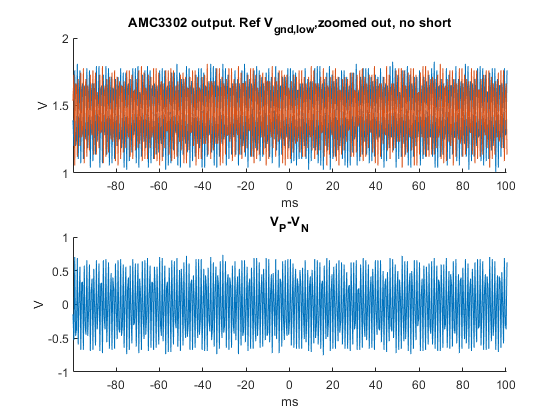
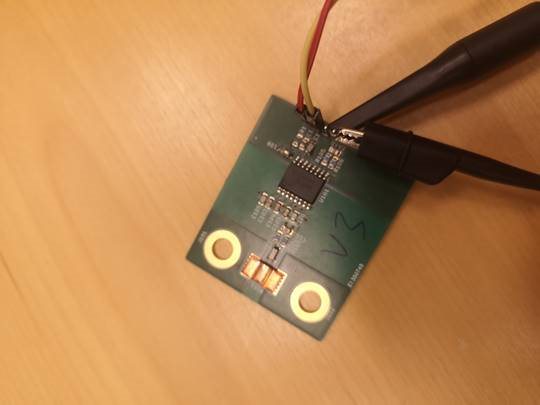
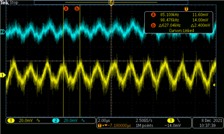
Fig 1 is the measured output of the pins via an oscilloscope.


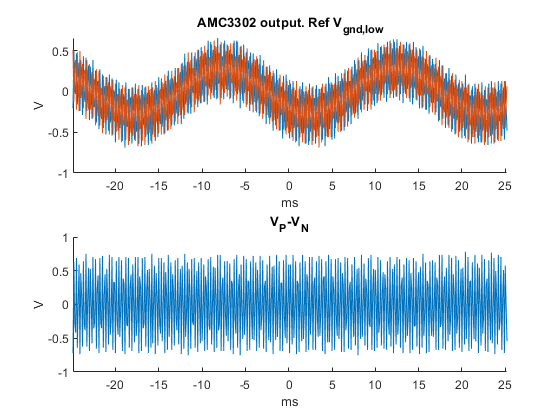
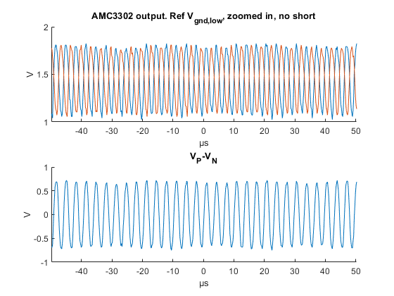
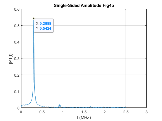
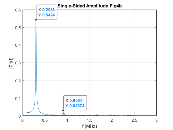
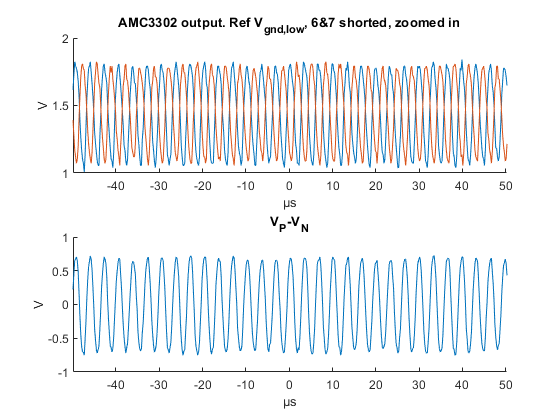
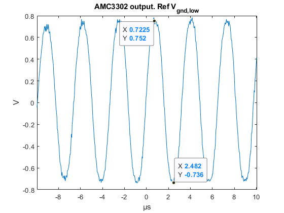
Fig 2 is zoomed in time base where you can see there is 300kHz noise of approx 500mV, or rather, not noise, but a sine.


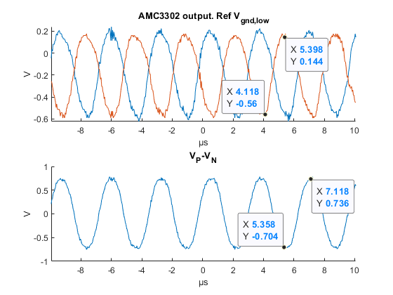
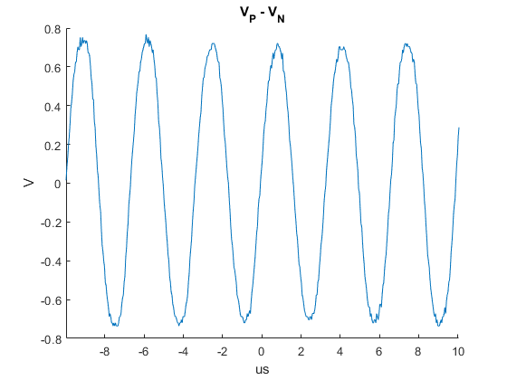
Fig 3 is where they have measured the output differentially, meaning V_P minus V_N


Ideally, according to the datasheet it should be a flat value, but as you can see it has an almost 600mV sine. The circuit supply is a 9V battery which is regulated down to 3.3 V using some diodes.

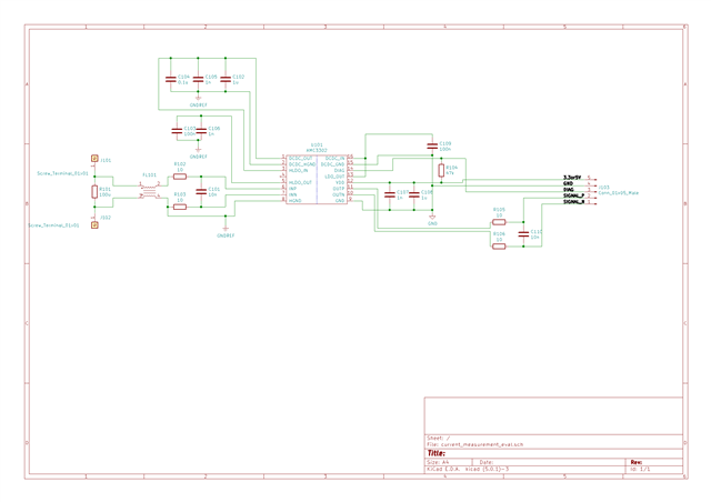
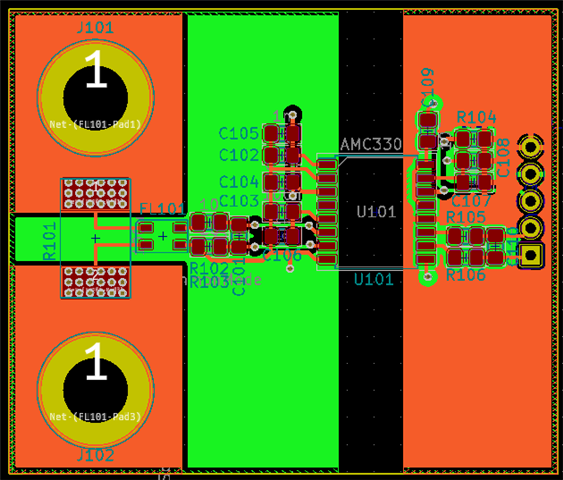
The current shunt is not connected to anything and is in the air and terminals J101 and J102 are not connected to anything.

Thank you for the help.

Regards,
Carlo

  • Hi Carlo,

    Thanks for reaching out with the AM3302 question!  What is the blue trace in 'Fig 1' above?  The orange looks like a 50Hz sine wave. 

    There is a chopper in the final stage of the AMC3302, but that usually shows some small ripple at ~625kHz.  What you show above is pretty excessive.  Can you short pins 6-7 and grab another screen shot of the outputs?   Differential is fine, but if you can get Voutp and Voutn to GND too that would be great.

  • Hello Hendrick,

    You are correct there was a superimposed 50 Hz sinusoid in the previous measurement.

    According to our customer, they have re-done the measurement with the same circuit under following conditions

    • 3.3V DC supplied by a battery (voltage is regulated via series diodes)
    • No physical connections on terminals J101 and J102

    Fig 1. Zoomed out.
    Top figure 1 is Pin 11 (V_P) vs Pin 15 (DCDC_GND) and Pin 10 (V_N) vs Pin 15 (DCDC_GND).
    Bottom figure 1 is DC V_P minus V_N, performed in Matlab.

    Fig 2, same as Fig1, zoomed in:


    Fig 3. Same as Fig1 but, as requested Pin 6&7 shorted

    Fig 4: same as fig 3 but zoomed in

    The frequency of this oscillation is around 300kHz as can be seen by the FFT of Fig 4B.

    Regards,
    Carlo

  • Hi Carlo,

    So, can you tell us what else is in circuit here?  If the above plots are via MatLab, how are you getting the actual outputs of the AMC3302 into the PC?  Can you look at the pins directly with an analog o'scope and let us know what you see?

  • Hello Tom,

    Our customer is connecting the probe at the output of the pin header (to the right on the pcb). Here are the other details:

    Interestingly, I have found that the average of the output seems to follow any voltage biasing of pins 6-7. But there is still a quite noticeable high frequency noise of about 0.6Vpk. I have seen that the noise comes directly from the pins and is not an environmental phenomenon. I have among other things tried changing from an isolated DC source to a battery and reduce the feeding wire length and twinning it.

    I have tried soldering 3 different boards. So it’s not an individual issue rather an issue with the application of the chip here. Or maybe I’m using the chip in a wrong way. Another interesting feature is that the behavior of the sinusoid seems to change with applied DC voltage to DCDC_IN (pin 15). The peak to peak does not change.

    Please see the attached pictures of measurement setup and the measured values at this time instance.

    Regards,
    Carlo

  • Hi Carlo,

    What does VOUTp look like if the probe is actually tied to GND rather than VOUTn as is shown in the picture above?

  • Hello Tom,

    Based from our customer, the voltages related to GND are posted as follows:

    Regards,
    Carlo

  • Hi Carlo,

    From the schematic and layout you posted earlier, I don't see anything that would cause a 600mV @ 300kHz oscillation like what you have pictured.  It looks like you've pretty much followed the recommendations in the SBAA515 document.  Under similar conditions the outputs of our AMC3302EVM look like this:


    Blue is VOUTp and yellow is VOUTn.  Here you can see the 625kHz chopper frequency and ~40mV pk-pk ripple.  Can you get an analog scope capture without any post processing?

  • Hello Tom,

    According to our customer,  he is not processing any of the measurements in a digital oscilloscope but simply capturing it and plotting the data in Matlab.

    Here are the other details provided: The only manipulations that are happening is where I expressed it (Ie deducted V_P from V_N and an FFT). It looks exactly like that on my screen as shown in the uploaded plots. I can find an oscilloscope and prove it to you if you would like. I also tried to measure with differential probes to circumvent any unforeseen grounding issues. Since I have tried 3 different AMC3302 chips. I am leaning towards the fact that it might be the PCB that is wrong but I cannot find what would be the issue. Do you have any tips what I should lookout for?

    Thank you for your continuous help.

    Regards,
    Carlo

  • Hi Carlo,

    Why not order an AMC3302EVM and see if you see any difference with our PCB?

  • Hello Tom,

    Our customer has already ordered the EVM and is currently conducting testing. Thanks for the suggestion.

    Regards,
    Carlo