This thread has been locked.

If you have a related question, please click the "Ask a related question" button in the top right corner. The newly created question will be automatically linked to this question.

Voltage amplifier piezo sensor/disc with subsequent ADC

Other Parts Discussed in Thread: INA326, TLV2771, INA327, TPIC8101

Hi everybody,

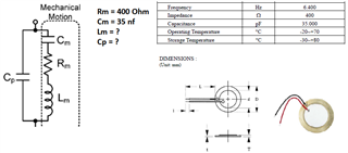
I want to build a simple voltage amplifier circuit for a piezo-ceramic slide/sensor (sensor data see attached pdf).

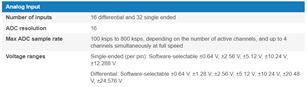
The sensor is to record sound in a frequency range up to approx. 20 kHz. The amplified signal shall be input to a rapid control prototyping system. There a 16-bit ADC is available, whose voltage range can be configured optionally +/-0.64 V, +/-2.56 V, +/-5.12V, +/-10.24 V (see picture). 

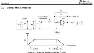
The amplifier circuit should be quite simple and cheap, I thought for example a solution with the INA326/327 or TLV2771 if that is possible?

I am grateful for any help, thanks!

Felix

EKULIT-190031.pdf

  • Hi Felix,

    We may be able to assist you, but we will need to have more information. 

    Based on the EKULIT-190031's datasheet, it seems that resonant frequency is approx. 6.4kHz (which is a single frequency). Do you know if the piezoelectric transducer is able to response to sound from 10Hz - 20kHz range or some other frequency range? In addition, we need to know the inductance figure, Lm, of the transducer. 

    Further, we need to know what is the excitation voltage of the transducer. For instance, 

    1. If sound wave is able to change its 400Ω impedance under a given excitation voltage, then we may be able to build a Wheatstone bridge input circuit with INA326/INA327 or other instrumentation amplifier (if sound wave is generating a mechanical displacement within the transducer, which results in changes of the nominal resistance, then we know what to do with the impedance.). 

    2.   If sound wave is able to generate small voltage across the transducer's leads, we may be able to amplifier the response signal, say TLV2771 or others. 

    Can you tell us how the transducer works? 

    Based on the datasheet, my guess is that the piezoelectric transducer may require approx. 6.4kHz in order to resonate within the piezoelectric layers. In addition, I need to know the gains and linear displacement range before I am able to suggest series of selectable gain circuits to meet the output voltage ranges of ADC converter. 

    If you have an example of the application, please let us know. Maybe we are able to figure it out. 

    Best,

    Raymond 

  • Hi Felix,

    I may be able to estimate the inductance of piezoelectric sensor, if the resonance frequency is at 6.4kHz by f-r = 1/(2*pi*sqrt(LC)).

    Based on the equation, the Lm value is approx. 0.0177H or 17.7mH. 

    The sensor is to record sound in a frequency range up to approx. 20 kHz. 

    It is not clear that the piezoelectric sensor is able to use as microphone, but it is certainly that it can produce audio sounds (may not be the entire audio range). 

    I would suggest to characterize the sensor with a simple circuit. Once you understand the sensor's characteristics, I can help you to put a circuit together for an application. 

    If you need any assistant, please let me know. 

    Best,

    Raymond 

  • Hi Raymond,

    thank you very much for your help. I have asked the manufacturer of the piezo element for additional information, however, unfortunately there is no additional information besides the one page data sheet.

    Regarding the application of the piezo element: I would like to use the element to build a kind of trigger or microphone to detect the start/end of a combustion in a combustion chamber via acoustic signals.

    In the meantime I have additionally looked around for another somewhat more expensive piezo element (DT1-028K/L w/rivets 1-1002908-0), see data sheet. Would it be easier to build a kind of "microphone" with additional amplifier with this one, e.g. like the amplifier in the following picture, which is from the TI Report "Signal Conditioning Piezoelectric Sensors - Application Report SLOA033 - Sep 2000"?

    Best regards
    Felix

     ENG_DS_DT_Series_with_Riveted_Leads_A1.pdf

  • Hi Felix,

    I would like to use the element to build a kind of trigger or microphone to detect the start/end of a combustion in a combustion chamber via acoustic signals.

    Yes, this piezoelectric sensor may be used as microphone. The input impedance of the transducer is >1MΩ and its capacitance is approx. 1.4nf. TLV2771 is a high input impedance op amp and should work well for the type of piezoelectric sensor/microphone application ( and low cost).

    My guess is that the previous piezoelectric transducer may be used as beeper or buzzer. 

    I think that you need to get the piezoelectric or similar sensors, and characterize the transducer near the combustion chamber.  We need to have data about its input amplitude and op amp gain settings (the datasheet is very general about its performance characteristics).  The piezoelectric transducer's output voltage is a function of sound pressure wave and circuit input impedance. If the audio sensor is operating in the vicinity of an op amp, we may simulate the circuit with voltage mode amplifier circuit. Or we may use the charge mode circuit as you posted above. 

    I believed that TLV2771 is supported by general purpose op amp team. If you need a close support, we can transfer you there.  In the precision op amp team, we have similar products such as JFE2140, or other high input impedance amplifier that may work with the application.  Since this is a low cost application, TVL2771 may be more applicable.

    Best.

    Raymond 

  • Hi Raymond,

    thank you very much for the valuable tips. I will next try to characterize the piezo element a bit more precisely in the lab and will then contact the op amp team if necessary.

    Best regards
    Felix

  • Hi Felix,

    you might find this link to the TI's knock sensor interface TPIC8101 useful:

    https://www.ti.com/product/TPIC8101

    Kai