Hi, Team
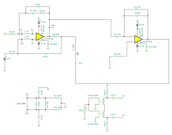
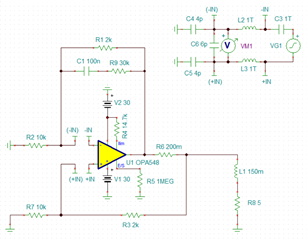
I'd like to use OPA548 to build a bridge Howland current source, the schemaitc is posted as below. In the application the load is a coil, the series R8 and L1 is its equivalent circuit model, R8 is 5Ohm, and L1 is 150mH
Here are a few of my questions,
1. How to analyze the circuit's loop stability with TINA-SPICE?
This circuit is composed of two typical sub-circuits, improved howland current source and inverting amplifier, right now I just analyze the loop stability of these two sub-circuits separately, is this reasonable? is there any other way to analyze the loop stability for this ciurcuit?
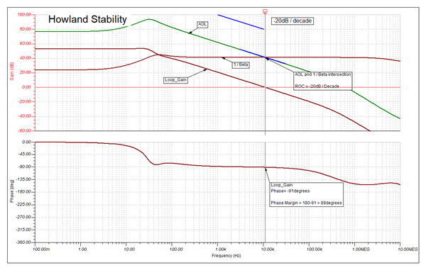
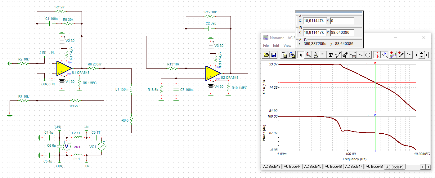
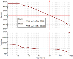
2. Loop stability simulation of Howland circuit
The simulation circuit and result are shown as below, the frequency of input signal is 1Hz in the application, it seems the result looks good, the phase margin is enough.
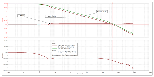
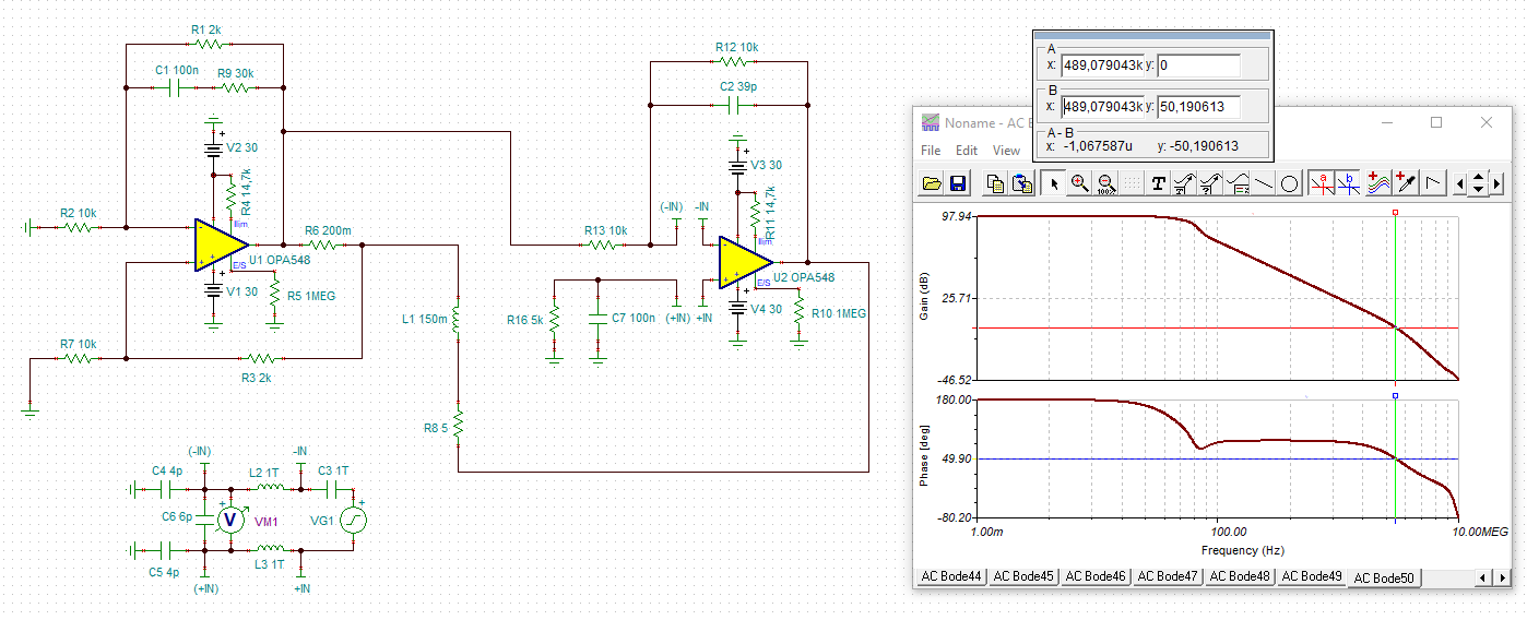
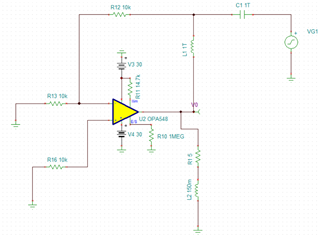
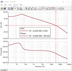
3. Loop stability simulation of inverting circuit
For this inverting amplifier, the load is a resistor in series with an inductor, the loop simulation result looks really bad, the phase margin is negative 342 deg? Is there something wrong with my simulation circuit? How to compensate this circuit to make it stable when the load is inductive? I've tried parallel some capacitors or RC to the feedback resistor, but it didn't work out.
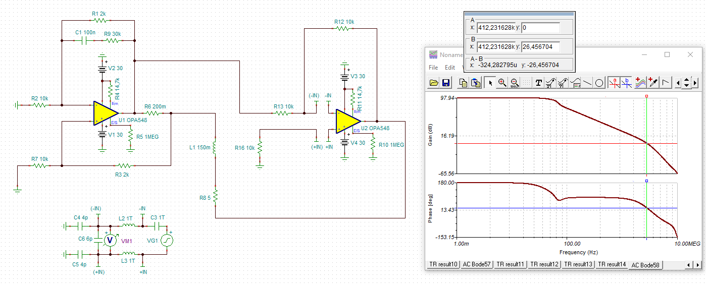
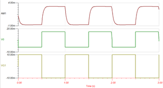
But then it is weird that the small signal transient response simulation result looks good, referring to the right bottom waveform, the input signal is a 1Hz/10mV pulse signal, the signals in the screenshot are output current, output voltage and input voltage from top to bottom. It complicts with the loop stability analysis, it seems the circuit is stable from the transient response simulation, I can't figure out why, can you help with this?
And finally, the relevant TINA-SPICE schamatic are attached.
loop stability simulaiton of OPA548 howland circuit.TSCCurrent-out Bridge drive with OPA548.TSCloop stability analysis with OPA548 inverting amplifier.TSC
Thanks for your help.
Best wishes.
Charlie Chen