This thread has been locked.

If you have a related question, please click the "Ask a related question" button in the top right corner. The newly created question will be automatically linked to this question.

INA190: IN190 low side current sensing

Part Number: INA190

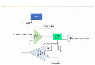
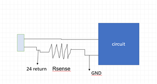
low side current sensing  and my load is GND .

we are sensing current through sensing resistor. the Common GND  for all circuit .

Unidirectional Mode and low side sensing 

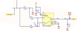
 this configuration of circuit is correct ?

  • Hello value engineer,

    This is a correct implementation for low-side sensing with INA190.

    Sincerely,

    Peter

  • hello peter,

    the above block diagram is the low side current sense using INA190.

    i have to measure the readback current of the my design.

    i have taken the load as a GND.

    i will measure GND to 24V  return  through sensing resistor .AGND and GND shorted 

    can i take this GND as load is it correct?

    i have the GND connected to  reference pin  is correct?

  • Hey Kishore,

    This should work. As long as the input sense voltage (Vsense = V_IN+ - V_IN-) is > 0 and the input common-mode voltage (VCM) is >=-0.1V, then device will operate as specified. In your diagrams I would assume that current flows from circuit GND to 24V_RTN and this would create a Vsense>0.

    The INA190 is bidirectional and can measure Vsense<0, but only when REF >0. If there is any chance that current be negative or if the current you need to be measure become very small and INA190 output (Vout) goes outside of linear operating region and thus saturates or too much error is accrued, then it can be helpful to provide a small bias voltage to VREF. However, it seems at 4mA, Vout should be high enough. Vout_low = 4mA*3.92Ω*25V/V + VREF = 392mV > 100mV, where 100mV is the low end of the specified operating range for specified gain error (see section 6.5 of datasheet).

    I would check to make sure there is no inductive kickback in the VCM where VCM could go below -0.1V or -0.3V. If VCM goes below -0.1V, then device could operate inaccurately. If VCM goes below -0,3V, then device could become damaged. If this is possible, then add input resistors to try to limit current to < 5mA max  (see section 8.1.3 on the sizing of these resistors and the error they generate). Usually clamping diodes can be used to protect device and clamp VCM, but this is really only practical for positive VCM transients exceeding the maximum VCM of 42V (see section 8.1.4 of datasheet).

    Hope this helps.

    Keep in mind that we have = training videos to educate on how to use our devices as well as other amplifiers and ADCs.

    https://training.ti.com/ti-precision-labs-current-sense-amplifiers-gain-error

    Best,

    Peter