This thread has been locked.

If you have a related question, please click the "Ask a related question" button in the top right corner. The newly created question will be automatically linked to this question.

TLV4112: Sallen Key Filter Stability

Part Number: TLV4112
Other Parts Discussed in Thread: TINA-TI, LM7332

Hi,

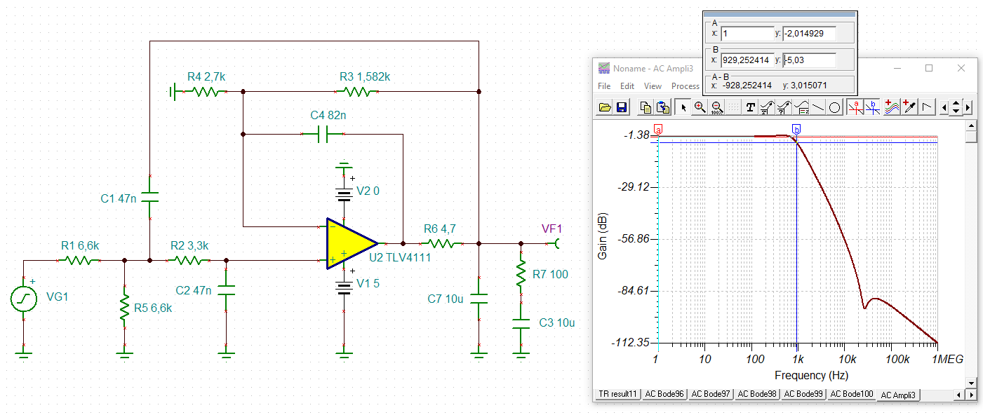
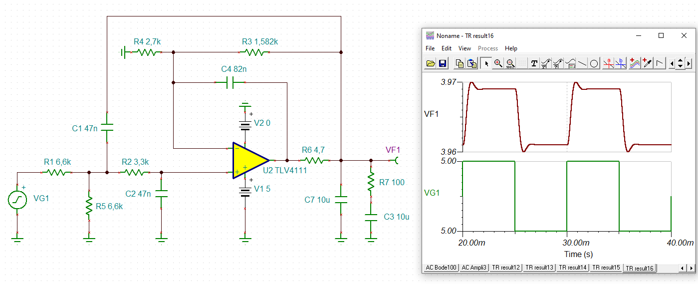
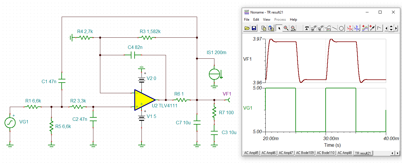
I'm interested in using the TLV4112 amplifier (for its high output current) in a Sallen Key low pass filter unity gain configuration. The cutoff frequency is 1kHz. 

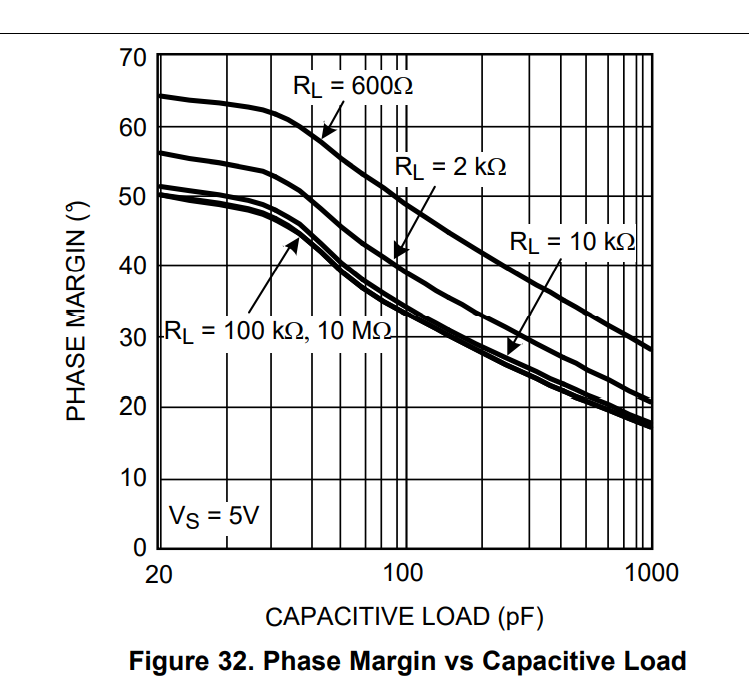
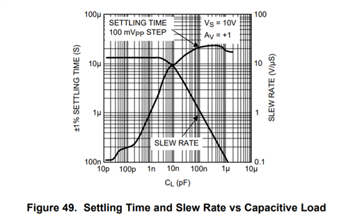
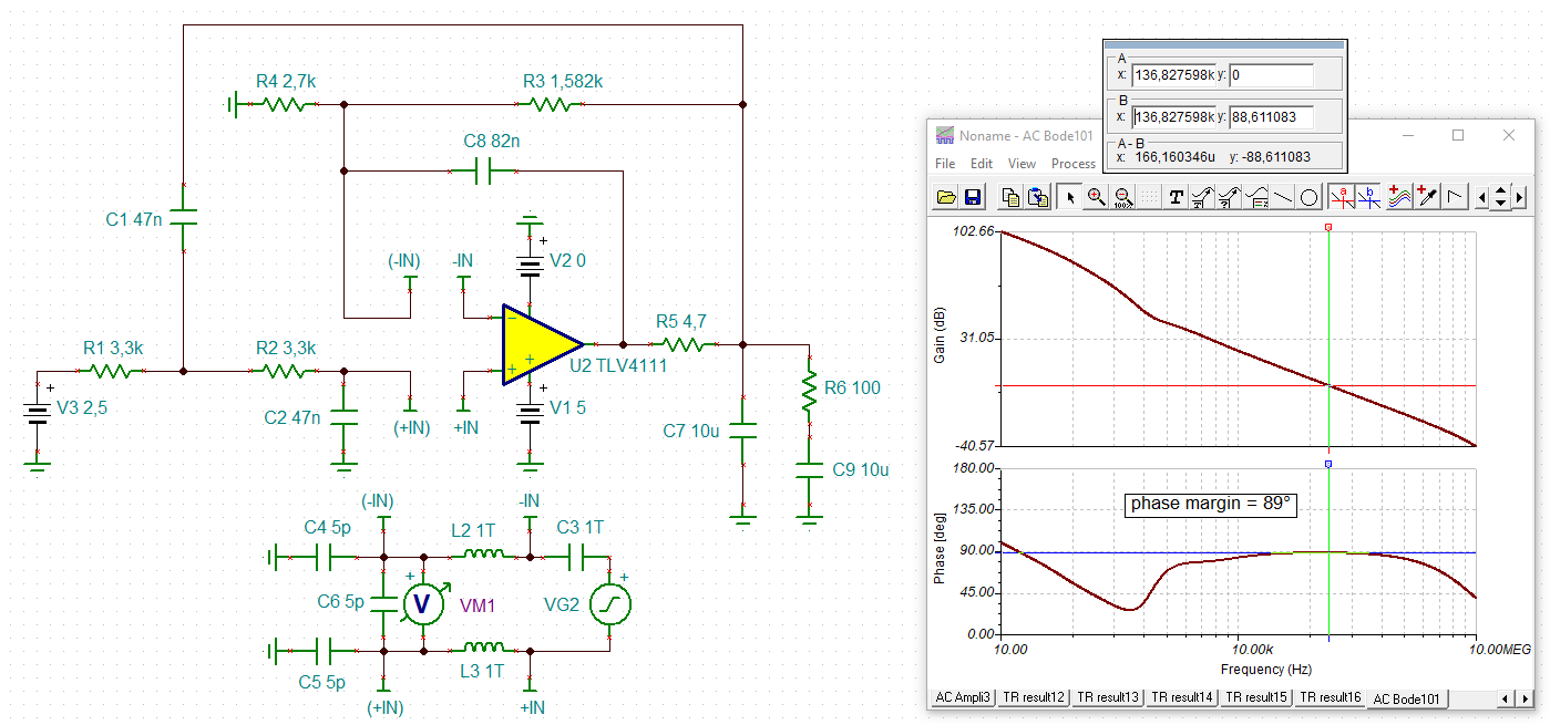
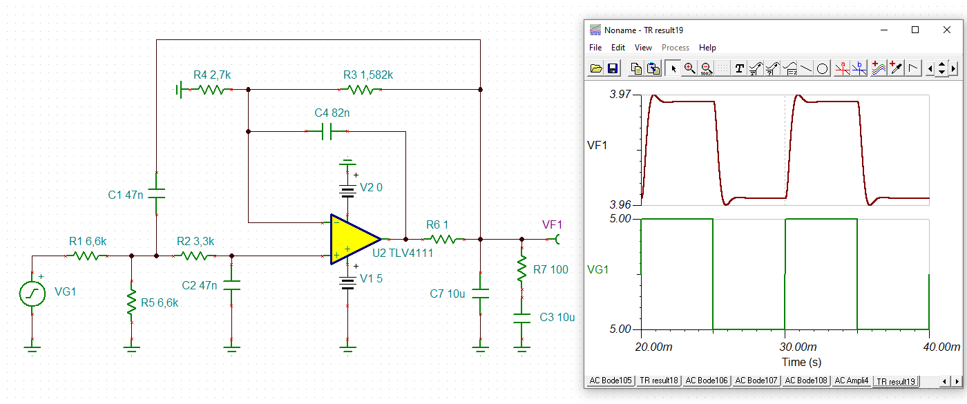
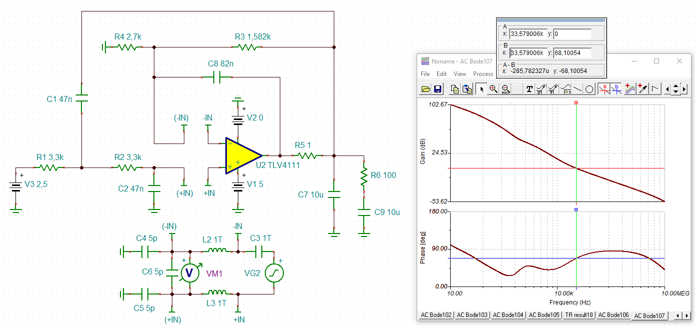
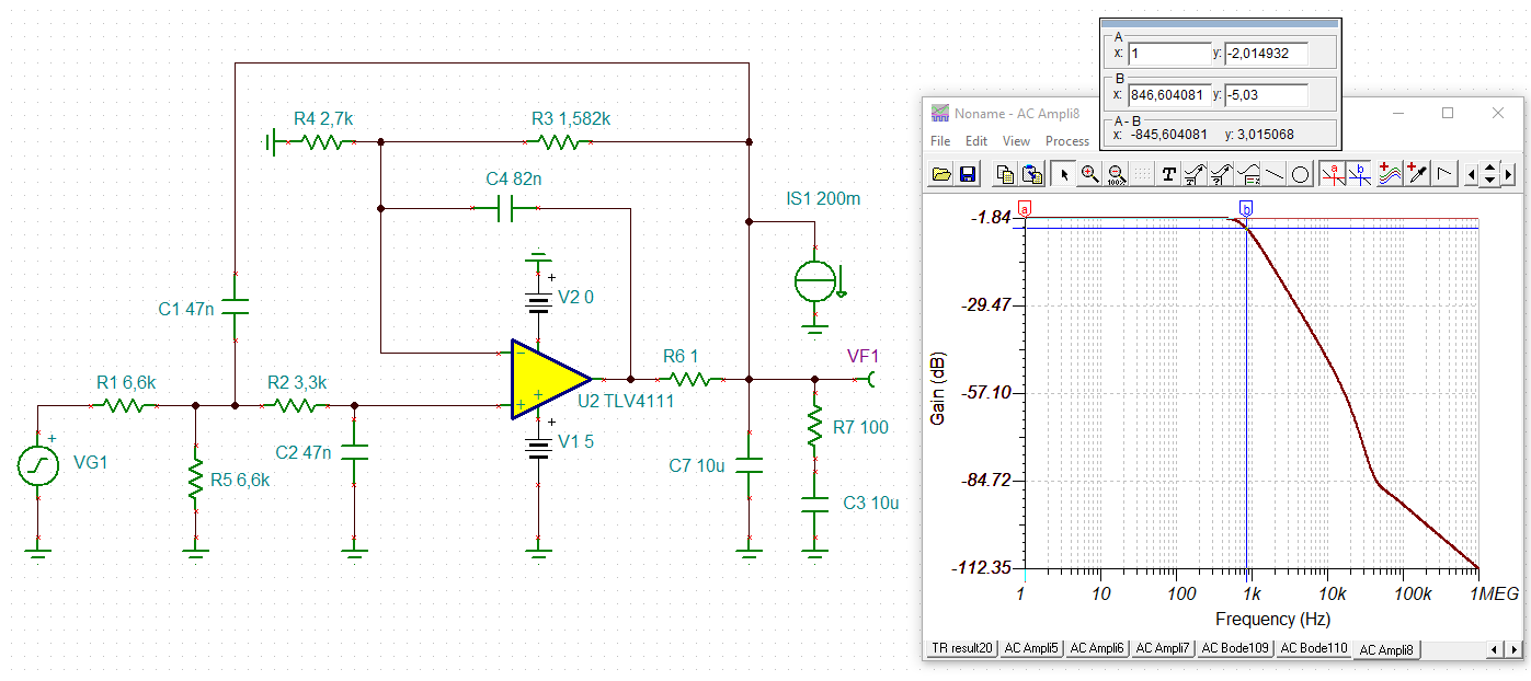
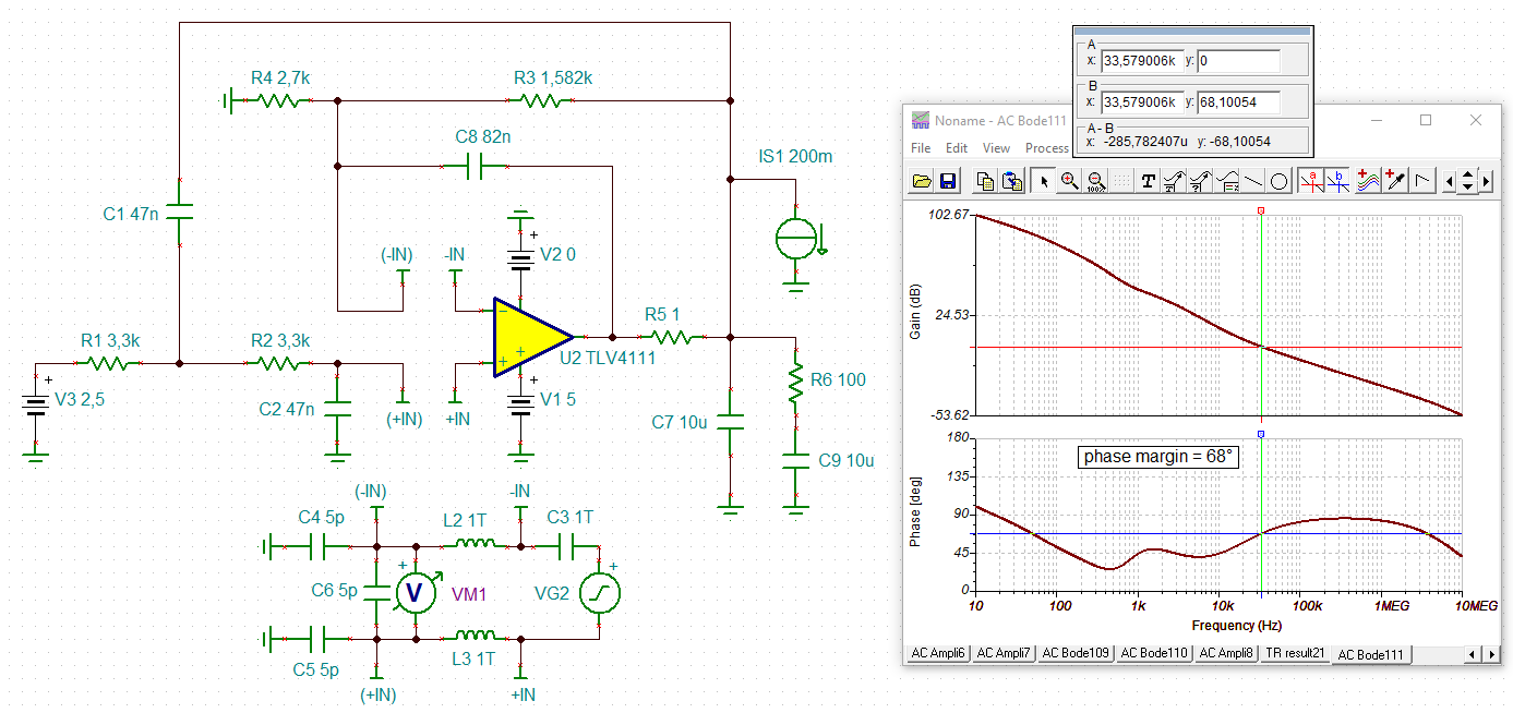
The op-amp is stable in the unity gain, but cannot drive "unlimited" capacitance. I have a capacitor in the 10-20uF range downstream from the output of the filter. My question is, will the design be unstable because of the large amount of load capacitance? How would I go about verifying the stability of the design?

Thanks.

  • Hi Stanley,

    An output capacitance of 10 uF to 20 uF is an exceedingly large load for an op amp to drive. The Sallen-Key filter should be stable alone, but adding the very high load capacitance will likely cause the op amp to become unstable. Sometimes the equivalent series resistance (ESR) of the large output capacitor work in conjunction with the capacitance re-stabilize the op amp, but in doing so the bandwidth of the circuit becomes unacceptably lower. Therefore, the op amp would have to rely on another stabilization technique to be stable.

    Since the application is a Sallen-Key active filter that has a specific and defines response ideally, the ways to stabilize the stage are very limited. The TLV4112 datasheet in the "APPLICATION INFORMATION - driving a capacitive load" section discusses adding an RNULL in series with the output to isolate the capacitive load. This is a common stabilization technique, but RNULL and the CLOAD create an RC low-pass filter at the output. The result for your circuit would be the intended Sallen-Key active filter, followed by the RC low-pass filter. For example, if  RNULL is 10 Ohms and CLOAD is 10 uF, the -3 dB cutoff of the RC filter would be 1.59 kHz. Since your active filter has a cutoff frequency of 1 kHz following it with the 1.59 kHz filter will result in a filter response that is the product of the two responses. That may, or may not be acceptable.

    If you have a schematic for your TLV4112 Sallen-Key filter and the proposed large capacitive load I could do a stability analysis using TINA-TI. Almost certainly the circuit will require some amount of RNULL resistance to attain a usable phase margin. If you provide the circuit schematic we can see what the circuit does in simulation and determine if it can be adequately stabilized.

    Regards, Thomas

    Precision Amplifiers Applications Engineering

  • Hi Stanley,

    Additionally, is there going to be any other kind of load in parallel with the large load capacitance at the TLV4112 output? If there is that could increase, or may decrease the phase margin.

    Thanks, Thomas

    Precision Amplifiers Applications Engineering

  • Hi Stanley,

    why not showing a schematic?

    Kai

  • Hi Thomas,

    Thanks for the quick response, it was very helpful. I won't be able to go too much more details on the design. One thing I noticed was that there are Op-Amps advertised as "unlimited capacitive" drive like the LM7332. What does that really mean? Figure 32 shows that the phase margin is down to <20° at 1nF 10MΩ. Technically it is still is stable, but it is not something I would like to use with low phase margin. What happens to this Op-Amp with a 10uF load?

    Thanks,

    Stanley

  • Hi Stanley,

    in any case you must run a phase stability analysis. We could do this for you, if desired.

    Kai

  • Hi Stanley,

    The LMC7332 and other op amps having the ability to remain stable and "drive unlimited capacitive loads" are produced by TI's General Purpose Op amps division so the expertise for those product resides with them. They are certainly more expert regarding their characteristics than I am.

    What I do see from the LMC7332, datasheet Figure 49, is that the slew rate (SR) decreases with increased load capacitance (CLOAD). Since there is the a direct relationship between SR and bandwidth:

    SR = 2 pi x F x Vpk    then,

    F = SR / (2 pi x Vpk)

    Therefore, the bandwidth of the op amp must decrease as CLOAD becomes larger. I believe what occurs with this class of op amps is the output load capacitance re-compensates the op amp moving its dominant pole response lower in frequency. That lowers its bandwidth.

    The old proverb sates "there's no such thing as a free lunch." That appears to be the case for this class of op amps as well.

    If you provide your circuit we can run a stability analysis as Kai and I have offered.

    Regards, Thomas

    Precision Amplifiers Applications Engineering

  • Hi Thomas,

    Thanks for all the good responses. I have another question regarding the open and/or closed loop output impedance of the LM7332. The data sheet looks to have one data point for closed loop output impedance of 3Ω at 100kHz. Is there any data near DC? I am interested in the output error due to the closed loop output impedance when drawing a constant load of 50mA. In the simulations it looks to be quite significant.

    Thanks,

    Stanley

  • Hello Stanley,

    As mentioned, the LM7332 is supported by TI's General Purpose Op amp division and we don't have any additional information for the amplifier here in Precision Amplifiers.

    The ROUT listed in the Electrical Characteristics table is a closed-loop, gain of +1 V/V output impedance specification. If this had been an open-loop measurement which we refer to as Zo and that number would be much higher. Today, TI provides the Zo vs frequency graph in most op amp datasheets. The Zo curve can be very different between different op amps because its characteristics are very design dependent. However, even if the frequency is moved downward from 100 kHz to something approaching DC, the Ro tends to be very low because of the very high open-loop gain (Aol) at the lowest of frequencies and DC. Once the loop is closed the Ro is often in the tens, or hundreds of milliohms for many op amps.

    Unless the General Purpose Op amps group has measured the Zo vs frequency for some other purpose that data may have not been taken. I suggest you contact them via their e2e forum and ask if they have any additional Ro or Zo information.

    Regards, Thomas

    Precision Amplifiers Applications Engineering

  • Hi Thomas,

    I'm not sure how to navigate to their e2e forum. Can you comment on how to get there?

    Thanks,

    Stanley

  • Hi Stanley,

    I have moved this e2e thread over to the GP Amps e2e. Good luck with your design.

    Regards, Thomas

    Precision Amplifiers Applications Engineering

  • Hey Stanley,

    For the LM7332, the open loop output impedance was not something that was measured, however we can calculate the Z0 using figure 29. At 1kHz the Zo is 15kOhms, and probably increases as frequency lowers. Thomas is correct that the "unlimited" cap load comes at a bandwidth cost. Additionally, you can increase the cap load drive with compensation techniques, but 10-20uF is a significant cap load.

    Do you have a circuit schematic we can use to simulate? Many of our newer devices have the Zo modeled, and will have effective stability simulations

    Best,
    Jerry