Other Parts Discussed in Thread: LM7705, , OPA1671, OPA376, TLV376, TINA-TI, TLV8812
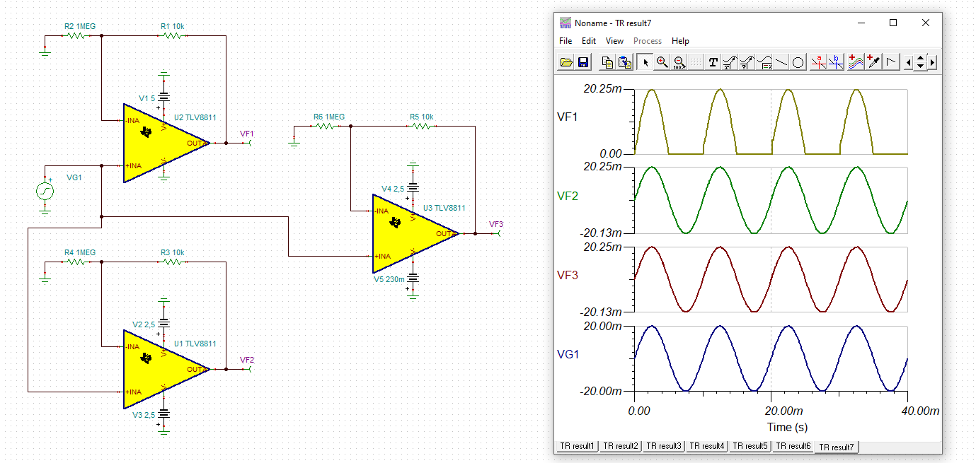
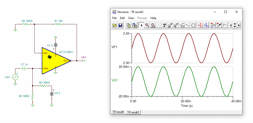
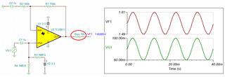
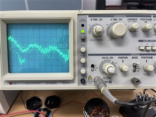
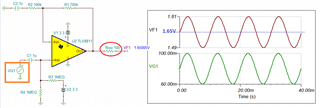
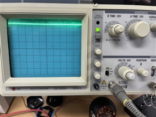
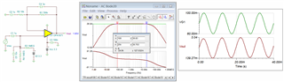
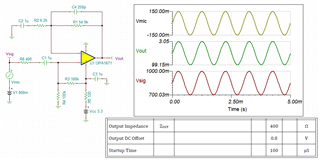
The output of the non inverting amplifier does not come out.
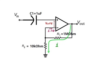
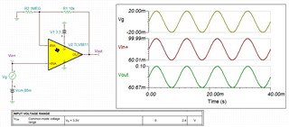
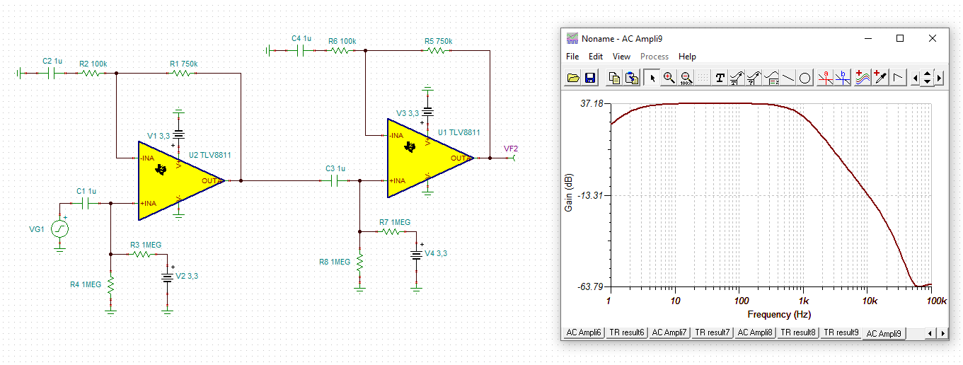
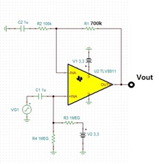
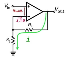
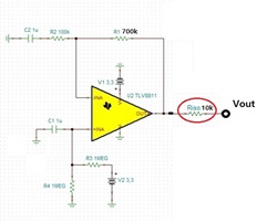
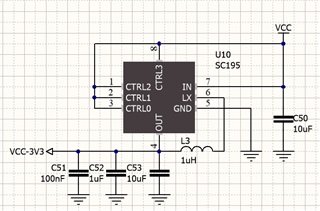
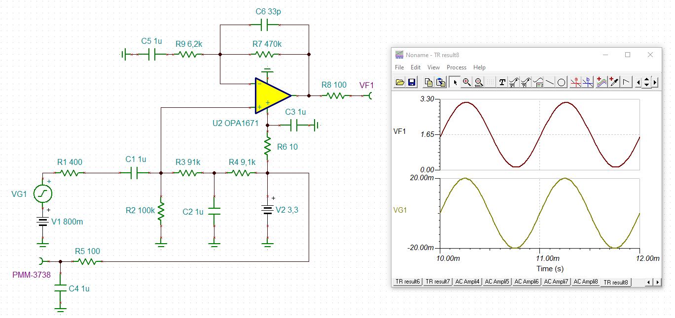
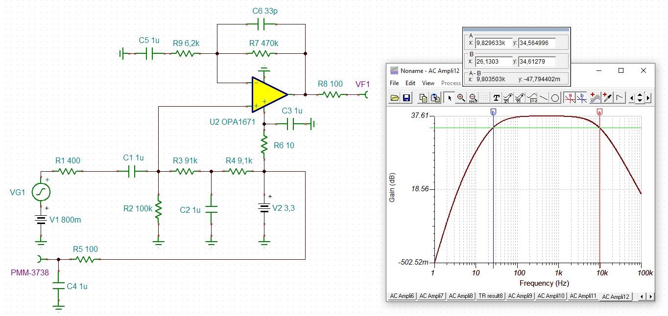
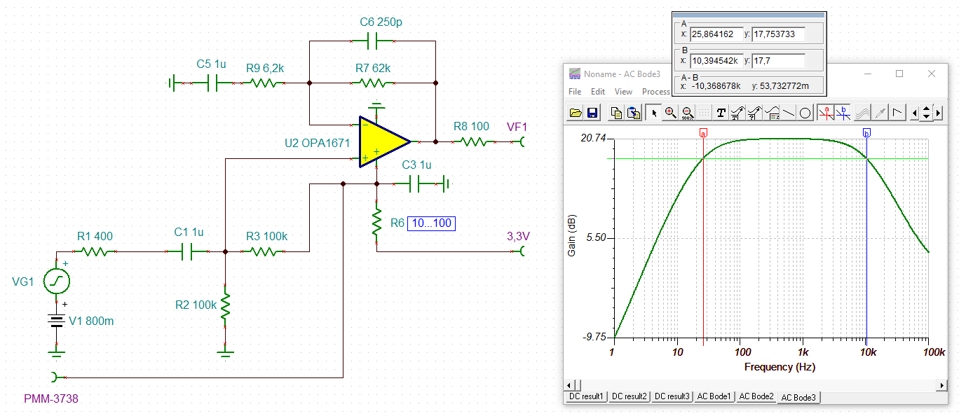
The circuit diagram is shown below.

Rf is 1MOHM and Rg is 10kOHM.
Vin has a waveform between +20mV and -20mV.
How should I decorate the circuit diagram?
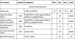
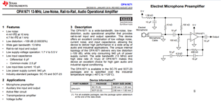
The opamp chip is TLV8811DBVR.