This thread has been locked.

If you have a related question, please click the "Ask a related question" button in the top right corner. The newly created question will be automatically linked to this question.

OPA192

Part Number: OPA192
Other Parts Discussed in Thread: TINA-TI

Hello,

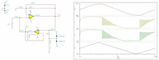
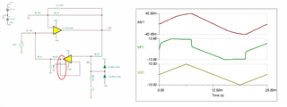
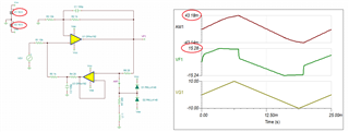
Problem with Howland current pump with buffer circuit.

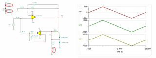
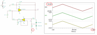
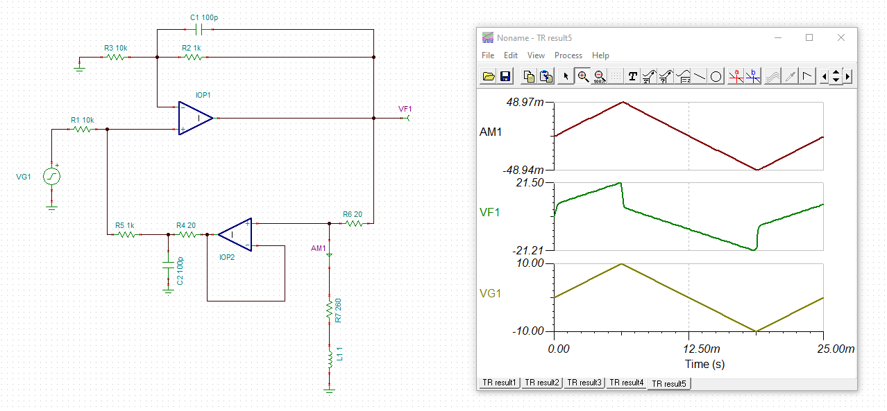
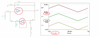
The +50mA/-50mA current generator allows to supply a valve simulated by a 1H choke and a 260R series resistor. The assembly is not stable. You will find attached a simulation. How is it possible to stabilize such a circuit?

Thank you for your help

OPA192.docx6064.OPA192.zip

  • Hi Druilhe,

    I have confirmed the problem you report with your circuit - see below.

    There are three main reasons behind the issue you see with your circuit:

    1. First, to get the benefit of R4 20ohm series resistor, the feedback should connect in front of the resistor to isolate the capacitive load - see below.

    2. In order to sink/source 50mA, supply voltage must be at least 2.5V higher than the required output - see below.

    Therefore, considering that under +/-50mA steady-state load VF1 needs to get close to +/-14V, you must use a minimum +/-16.5V power supplies. However, this is not enough - at 40Hz frequency you use, the impedance of 1H inductor is 251ohms resulting in gross distortion - see below.

    3. Thus, in order to solve the issue you must also lower the value of inductor you use (see below)

    or you need to lower the frequency of the input signal - see below.

    Below I have attached Tina-TI schematic for your convenience.

    Druilhe OPA192 Howlland current pump.TSC

  • It is not possible to decrease the self by 1H and the series resistance by 260R. Do you have another amp that can work on this principe with +/-50mA with a +/-15V supply. A stable amp with this principle of operation.

  • Hi Druilhe,

    as Marek mentioned, this is impossible with a +/-15V supply:

    drui_opa192.TSC

    Kai

  • By using ideal op amps Kai showed above that in order for the circuit to work as you envisioned with 1H inductance,  VF1 output would need to go to 21.5V, which is physically NOT possible on +/-15V supplies.  However, slowing the signal would allow it to work with VF1 of +/-14V - see below.