This thread has been locked.

If you have a related question, please click the "Ask a related question" button in the top right corner. The newly created question will be automatically linked to this question.

INA240EVM: What PWM Rejection mean in the Spec

Part Number: INA240EVM
Other Parts Discussed in Thread: INA240,

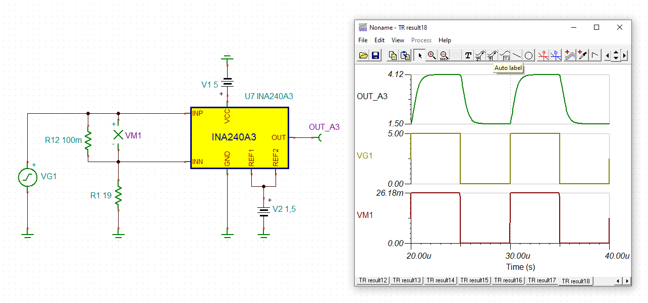
Excuse this somewhat rooky question.  I am a retired systems engineer who now develops electronic 'features' at our local model town.  Some years ago, I developed a model train controller using PWM to control speed.  Unfortunately one of the staff accidentally shorted the Motor Drive Board and destroyed it.  I and another volunteer at the model town, decided to add an over-current circuit, but this has proved harder than I expected owing to the fact that the current is pulsed and traditional sense amplifiers reproduce the pulses exactly.  We saw that the INA240 offered PWM Rejection, so we bought an EVM to try it out.  Here is the circuit that I've used to prototype the over-current Module:

I have a dual Bench PSU that produces the 15 V Drive for the PWM and the 3.3 V for the INA240EVM.  The Function Gen is a cheap hobby type but it seems to produce a clean output.  I set the Function Generator to provide a 5 V rectangular wave with a 2.5 V offset at 10 kHz, the PWM Modulator is a MOSFET and I monitor the INA240EVM output using a fully isolated scope.  Unfortunately, the signal appears as a DC level with the PWM pulses superimposed on it.  I was expecting the output to be more like the signal shown in Figure 9.4 in the Data Sheet.

Is there something fundamentally wrong with my test circuit, or have I misunderstood what the INA240 is supposed to do?

  • Hi,

    Indeed there could be a misunderstanding regarding what type of input PWM the device is supposed to reject.

    The text in the picture is blurry and I can’t quite make out the description for the load. But if the load is resistive in nature, then the load current, and consequently the shunt voltage, would all be square-shaped.

    INA240 rejects PWM common mode input voltage only, but ideally it should pass and amplify differential input voltage faithfully. If what the scope shows is an amplified version of the differential input (ie shunt voltage), then INA240 is doing what it is supposed to do.

    Regards, Guang

  • Hi Terence,

    ideal common mode rejection means that if both inputs see exactly the same signal, the output voltage is zero. This seems to be obvious, but isn't at all, because many discrete amplifiers are not able to suppress common mode signals to an acceptable level and this the less the higher the frequency of common mode input signal is. The INA240, on the other hand, shows an awesome common mode rejection ratio of 132dB at DC and 93dB at 50kHz and behaves nearly ideal referring to common mode rejection. So there's only very little punch through:

    In the above simulation the differential input signal is forced to be zero because of R12 = 0. The input signal to the INA240 is a true common mode square wave of 100kHz !

    But, of course, if R12 is non-zero and the differential input signal is also non-zero, as in your measurement, the output signal will show strong output pulses, because the INA240 is doing what it is intended to do - amplifying the differential input signal.

    terence_ina240a3.TSC

    Kai

  • Thank you Guang and Kai. My problem was that I hadn't realised that common mode PWM signals were a problem and so misunderstood what the spec was telling me.