This thread has been locked.

If you have a related question, please click the "Ask a related question" button in the top right corner. The newly created question will be automatically linked to this question.

LM2903B: LM2903BQDDFRQ1 comparator

Part Number: LM2903B
Other Parts Discussed in Thread: LM211-Q1

Hi TI,

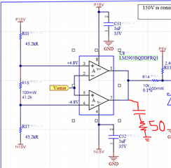
I am trying to design a comparator circuit with LM2903BQDDFRQ1 for over voltage and over current detection. The output voltage of a HAL sensor (which is AC) is fed to the comparator and if it goes out of range, it should notify the controller to take action.

The HAL sensor measures the output of an inverter which is supposed to be used as a power wall ( 110V nominal ). 

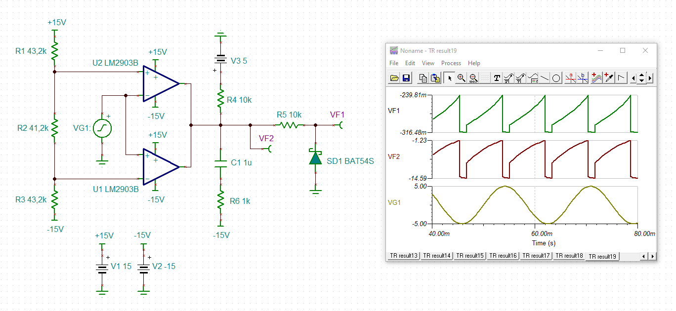
If the sensed voltage is in range (  -4.8 < Vsense < +4.8 ), the output is pulled up to 5V, otherwise it starts toggling ( since it is an AC signal ) between 5V and 1V ( from resistor voltage divider ).  But the controller requires a solid logic level for over voltage detection, either logic level low or high. How can I achieve that solid logic level and avoid the toggling ?

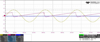
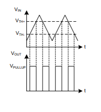
  •  Almost what I get at the output which I need to avoid the toggling 

  • Hi Mamzi,

    The ideal device for this application would be the LM211-Q1 - which is designed to operate on split supplies, but output a TTL compatible (0 to 5V) signal (open collector output). This eliminates the divider on the output.

    We normally do not recommend adding a capacitor to the output, but if you can add a capacitor that has a time constant long enough to keep the output low between the cycles.

    To quickly test in your circuit, add a capacitor between the outputs and V-. I would also add a 300 ohm resistor in series with the capacitor to limit the discharge current.

    The idea being, during "normal" times, the output is high and the capacitor charges to 20V through the pull-up and divider resistors. When the output goes low, the capacitor will quickly be discharged by the output going low (the output transistor "shorts" the capacitor going low). The capacitor then holds the output low as it slowly charges through the resistors for a bit until the output goes low again on the next cycle.

    How long the output stays low is determined by the RC time constant of the capacitor and all the resistors in series up to the 5V supply.

    This will also add a start-up time delay - so beware.

  • Paul,

    Thanks a lot for your help

    I added a cap a resistor at the output. And in case of having out of range sensed voltage/current, the output will be kept below 1v. Which is good.

    when the sensed signal barely gets out of range, the cap would have a very limited time to de-charge itself, therefore I couldn't keep it below 1v. to avoid that I reduced the resistor's value, on the de-charge path, from 300 ohm to 50 ohm and you see the result in the picture below.

    having a 50 ohm resistor for the de-charge path, 100mA of current flows back to the comparator, during the de-charge, 50mA for the output of each opamp. Do you think this current damages the output transistors inside the chip, which are open collector ?  In the data sheet "Short circuit sink current" is specified as 20mA for typical.

  • Hi Mamzi,

    I think Paul meant something like this:

    mamzi_lm2903.TSC

    Kai

  • Hi Mamzi,

    Kai got the slight difference. The cap should be across the output and V- so that the low impedance of the output transistor would directly short the capacitor (with current limited by the resistor), creating the fastest discharge. The divider also attenuates the "low" voltage.

    I guess your way is just as valid, only discharging 5V, but that also adds some inconsistency as are now stressing the negative supply and bypass caps during the discharge.

  • Paul,

    I agree that Kai's proposed circuit is way better than mine. In this way I can keep the output at a constant low voltage. 

    I'm just curious about the -15v in his schematic. Is the polarity of the battery connected to the jumper correct? 

  • Yes. He has the V2 battery set to a negative 15V (-15), which would place -15V on "positive" side of the battery, and place a negative voltage on the "-15V" node.

    If V2 were set to 15 (+15V), then it would be incorrect.

  • Thanks a lot Paul.