This thread has been locked.

If you have a related question, please click the "Ask a related question" button in the top right corner. The newly created question will be automatically linked to this question.

AMC3301EVM: AMC3301EVM spec.

Part Number: AMC3301EVM
Other Parts Discussed in Thread: AMC3301, AMC3336

Hi Team,

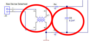
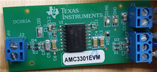
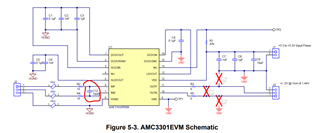
I ordered AMC3301EVM from digikey, looks there is some difference with the spec on TI website, for example the schematic's input side cap is C12, but on the board looks C8.

Could you let me know is the board newer or spec is newer, and how can I find the User’s Guide of the one I ordered?


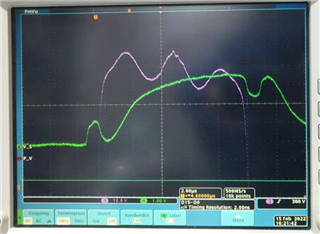
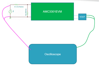
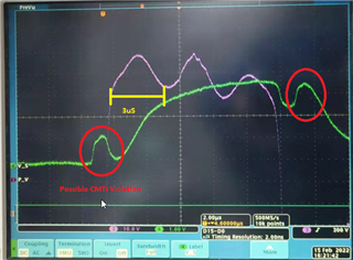
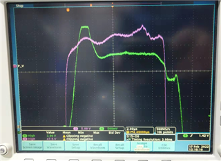
On the other hand, I have measured the output of AMC3301, as the following picture, purple is the primary voltage(390VDC, 10us pulse) I want to detect, green is output of AMC3301EVM.

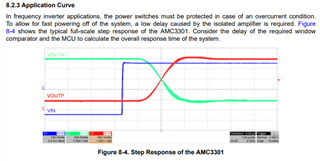
the EVM output rise time is too long and didn't following input's change. I guess maybe because of the evm's input filter, could you advice how to improve it to fit my application, thanks in advacne.


  • Hi Allen,

    We recently updated the AMC3301EVM and user's guide, the board you have is older and I've attached it's associated user's guide. sbau330b.pdf

    Figure 8-4 in the datasheet shows the expected step response, please note that the AMC3301 has a propagation delay of ~3uS. 

    While I agree that the input pulse has a duration of 10uS, the rise and fall time of the pulse is significantly shorter and the output catches the signal correctly about 3uS after the input pulse has settled high. The output pulse at the beginning and end of the input pulse looks like a possible CMTI violation (85 kV/µs), but I cannot confirm without seeing the full input waveform.  

    The input filter on the EVM you are using has a bandwidth of approximately 970kHz, so removing it may improve performance slightly. There is also a common-mode choke that you could consider removing, it's impedance over frequency characteristic is pasted below:

    I hope this helps and please let me know if you have additional questions. Furthermore if you believe the AMC3301 will not be suited for your application, please share more information about your application, accuracy and/or isolation requirements for this measurement, I would be happy to help you find a solution. 

  • Hi Alexander,

    Thanks for the information, I removed the choke and cap, EVM output rising time is reduced, but still look bad.

    The application is to detect the power supply of heater, a PWM signal controls 390VDC on/off , the minmum pulse width of the PWM is 10us, current in range 6A to 8A. The voltage 's flouctuation in range 380~400V in the 10us pulse, the target is to make a circuit to monitor the voltage.

    AMC3301 bandwidth is 334khz, not sure enough for this application, could you advise anything I can do to improve it, or is there any other better solution, looking forward to seeing your reply.

  • Hi Allen,

    Yes, it looks better now but still not perfect.

    Since the bandwidth is 340kHz and associated propagation delay is approx. 3uS, it takes 3uS for the filter to clear before the output is normal. The bandwidth of the AMC3301 cannot be modified as it is set be an internal digital filter. 

    What is your desired level of accuracy and delay time? Do you need a high level of accuracy or is an on/off indicator with a short time delay sufficient? 

    Do you have a sigma-delta filter module (SDFM) available on your MCU and is working with an isolated modulator an option? 

    The AMC3336 may be a solution: https://www.ti.com/lit/ds/symlink/amc3336.pdf

    This device has a high input impedance intended for voltage sensing and the bandwidth is set by the over sampling ratio (OSR) in the SDFM, up to 1.25MHz. 


    This increase in bandwidth comes at the expense of accuracy as discussed in this application note: https://www.ti.com/lit/wp/sbaa359a/sbaa359a.pdf

  • Hi Alexandra,

    Thanks for your recommendation, I think might need 0.1% accurate and ns level delay time,  at least 10MHz BW, I am looking at the high voltage probe circuit like the following link

    https://circuitcellar.com/research-design-hub/high-voltage-differential-probe/

    Do you think this will work if I build a similar PCBA in our machine, output connect to 16bit ADC and FPGA.

  • Hi Allen,

    I see, thank you for letting me know the requirements - they are very high but it should be possible with gain calibration. 

    Please let me know if you have additional questions about our isolated converters in the future. 

  • Hi Alexandra,

    Thanks for your help.