Other Parts Discussed in Thread: ADS127L01, , THS4531, OPA320
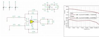
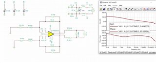
Please find THS4531A & ADS127L01 schematic snippet attached.
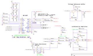
Using 10kHz test signal applied to PREAMP_P, PREAMP_M is set to GND, at C155 I see proper signal, but at net of R219/C152, I see 10khz signal, but with ~14MHz component on top, same at ADC_AIN+ output node.
What is root cause of this ringing, and how can I mitigate?
Thanks!
Schematic snippet:
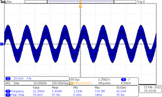
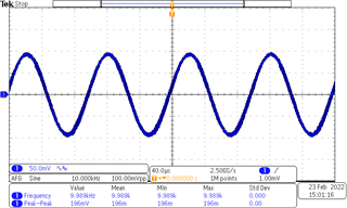
At C155:
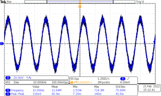
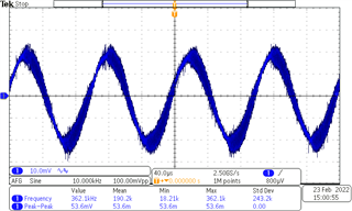
At R219/C152 node:
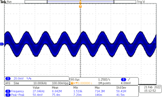
At ADC_AIN+ node: