This thread has been locked.

If you have a related question, please click the "Ask a related question" button in the top right corner. The newly created question will be automatically linked to this question.

TLV3603: The characteristics of the input diodes to meet the current limit to 10mA or less

Part Number: TLV3603

Hello,

My customer has been investigating TLV3603.  They saw the notes shown under the table of the absolute maximum ratings, so they'll have a schottky diode to meet the note, but they aren't sure which diode they should add without the characteristics of the internal diodes.  Would you please tell me the characteristics or recommend the external schottky diodes to meet the note (2) shown below?  Note that they downloaded the SPICE model, but it doesn't seem to support the diode.

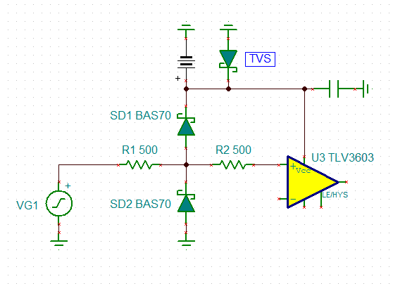
(2) Input terminals are diode-clamped to the power-supply rails. Input signals that can swing more than 0.3 V beyond the supply rails must be current-limited to 10 mA or less.

Best Regards,

Yoshikazu Kawasaki

  • Hi Yoshikazu,

    there's no simple answer. It depends on how much, how long and how often you intend to overload the input. In the simpliest case a 1k resistor will do the trick up to an overvoltage of 10V. For voltages up to 10V higher or lower than the supply voltage rails a 1k resistor will limit the current to 10V / 1k = 10mA. Keep in mind that the supply voltage regulators must be able to absorb this current without making the supply voltages rise to dangerous levels. Eventually, a TVS from the supply voltage rails to signal ground have to be added shunting the over-current to signal ground.

    You can increase the current limiting resistor. But don't overlook the input bias current of TLV3603 and its voltage drop across the current limiting resistor. 5µA times 1k gives 5mV which is in the same range as the input offset voltage of TLV3603. Increasing the current limiting resistor to higher values wil increase this error voltage as well.

    Another reason why it might not be a good idea to increase this current limiting resistor for a high speed comparator all too much is, that the current limiting resistor in combination with the input capacitance and stray capacitance forms a low pass filter eventually slowing down the TLV3603.

    Another option, for instance for situations when the input is repeatedly overloaded during normal operation, is to add external protection diodes like shown below:

    R1 limits the current through the protection diodes and R2 the current into the comparator. Because of the diode clamping only a fraction of the current is flowing through R2 while the most current is flowing through the protection diodes. This scheme allows rather small current limiting resistors and by this does not affect the speed of comparator all too much. At the same time, the current flowing into the comparator is heavily limited. Again, when the supply voltage rails cannot absorb the currents through the protection diodes, TVS should be added.

    From the standpoint of protection only, the current limiting resistor should be high. Then a simple resistor might be sufficient and a TVS not necessary. From the standpoint of speed only, on the other hand, the current limiting resistors should be low. So you will have to make a compromise.

    Kai

  • Kawasaki-san

    thank you for your post. 

    as usual, Kai’s response is extremely thorough and he’s offering great advice. Please follow his suggestions as needed. 

    thanks Kai for your continued support of the forum. 

    Chuck