This thread has been locked.

If you have a related question, please click the "Ask a related question" button in the top right corner. The newly created question will be automatically linked to this question.

LT1014-MIL: LT1014MFKB (5962-89677022A)

Part Number: LT1014-MIL

Hello

I have several questions for device 

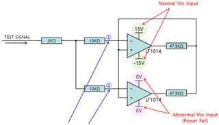
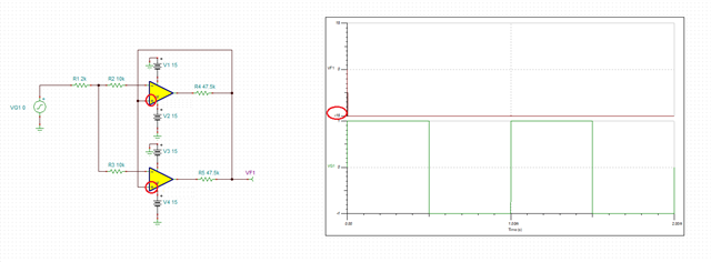
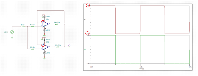
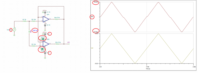
When the upper OP-AMP is a normal Vcc input and the lower OP-Amp is an abonormal Vcc input, the voltages at points 1 and 2 are not equal. Can leakage occur at the input of OP-AMP when the components power is not supplied?

If I use the LT1014MJB(DIP) package type,can the voltages at points 1 and 2 be the same?

Are the input characteristics of SMD Type and dip type devices different?

  • As shown in the absolute maximum ratings, the input voltage must not exceed VCC+. This implies that there are ESD protection diodes from the inputs to VCC+, i.e., a current will flow from the inputs into VCC+.

    The package does not make any difference.

  • Hi Rocio,

    what is the purpose of this strange looking circuit?

    Kai

  • Are you refering to the schematic? 

  • Rocio,

    For one, your circuit configuration has a positive feedback and thus the output will be stuck at one of the rails regardless of the input signal - see below.

    Therefore, to make any sense, you need to change the circuit to use a negative feedback so the output follows the input - see below.

    Having said that, each I/O pin has a ESD protection diode to its rails (see below).  Thus, powering down lower op amp will result in the input current, AM1, based on the input signal: AM1 =~ (VG1-0.6V) / 12k.  Therefore, the issue is NOT a leakage current but simply forward-bias current through one of the ESD diodes.