


Other Parts Discussed in Thread: INA823, INA125, TINA-TI
Hi team,
I want to design a Single-supply strain gauge bridge amplifier circuit using the op-amp OPA2180IDR.
The application note link is really helpful.
Attaching the specifications of the strain gauge.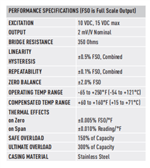
The excitation voltage is 12V.
The output voltage is 2mV/V
1). Does this means the output voltage swing will be 2mV only regardless of the excitation voltage range 10 - 15V?.
The Bridge resistance is 350 Ohms.
2). Does bridge resistance means the total voltage of the bridge or individual arms?.
When I connected to a 12V supply, a current of 34mA flows through the strain gauge.
3). Will this high current affect the performance of the strain gauge?.
Also when I limited the current through the strain gauge using a resister my output voltage swing is decreased.
As per the circuit diagram below,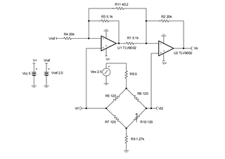
The opamps are powered from a 12V source.
My Vref is now set to 2.5V.
When Vref is set mid-supply (6V) my output voltage will be about 7V which is very higher than my input voltage range of the ADC - ADS1220IRVAT.
Under the balanced condition of the bridge, my output is about 2.9V, when strain is applied the voltage will be increased to about 4V.
4). Is there any chance the voltage at the output of the second opamp goes above a 5V range?.
5). Do you believe an instrumentation amplifier is better than this type of op-amp configuration?.
If yes please suggest an instrumentation amplifier suitable for my needs.


