This thread has been locked.

If you have a related question, please click the "Ask a related question" button in the top right corner. The newly created question will be automatically linked to this question.

INA240-Q1: Tolerance Calculation

Part Number: INA240-Q1
Other Parts Discussed in Thread: INA240

Hello Team, following question from customer:

Currently we are working on the worst case calculation.


For the tolerance calculation we have used the “current sense error analysis” from the TI homepage.


From our understanding the tool can just support a ground referenced output circuitry (starting with 0 A) for the error calculation.

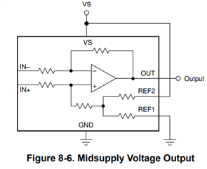
Since we are using the midsupply voltage output circuit, is there another version of the tool or setting available?

Our measurement range is between -40 A to 40 A (2.5V output = 0 A).


Could you also please help us to understand how the error characteristic and mechanisms are acting (e.g. biggest error at -40 A / at 0 A / …).


Many Thanks

Josef

  • Hello Josef,

    You could start with this tool and place the correct Rshunt value.  For the max error at -40A and 40 they are mostly due to gain error and can easily be seen with the calculator attached.

    https://www.ti.com/lit/zip/sbor020

    For the error at offset you need to account for VOS and the error in the resistor divider.  Vos can be seen in the calculator as well but harder to see as it would be down to 0A in the error plot.  https://training.ti.com/ti-precision-labs-current-sense-amplifiers-offset-error?context=1139747-1139745-1138708-1139852-1139851

    The link shows how to calculate it if you are adding CMRR PSRR and other error terms.

    As an example lets assume CMRR and PSRR are not a factor and you are using the same conditions as the datasheet of 5V supply and 12V VCM.  The offset is max of 25µV.  So the error at the output is 25µV * Gain of INA240 version you use.  I will use A2 version gain of 50 below.  And Rshunt of 1mΩ.

    The other error factor is reference error.  You assume it is 2.5V.  Lets assume that you have a 5V supply and the error comes from the resistor divider, any error from the power supply will also impact this.  You will have an error at the output of 0.1% of 2.5V.  Therefore the output error contribution is 2.5mV.  You would require to divide by the gain in order to calculate the error at the input.  

    So the reference error is 2.5mV/50 = 50µV.  Because the error of the reference and the VOS are uncorrelated you could use RSS to combine them.  If you want the worst case ever that would not be likely you can add them. RSS ~ 56uV.  Adding them is 75µV.

    If you use 56µV/1mΩ = 56mA of error at 0A.