This thread has been locked.

If you have a related question, please click the "Ask a related question" button in the top right corner. The newly created question will be automatically linked to this question.

OPA313: High accuracy current sensing under light load

Part Number: OPA313

Hi Team,

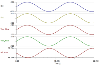
My cusromer has a request on current sensing, full load range is ±40A, and the sensing accuracy error needs to be below 1% when the load is within ±5A(light load).

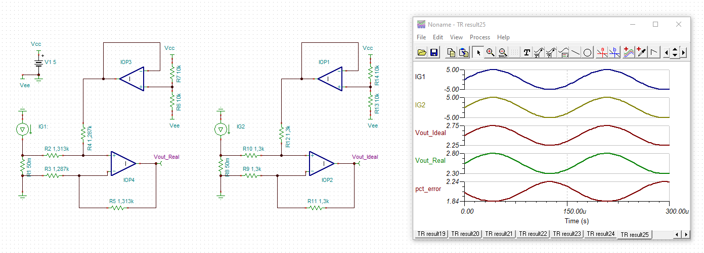
Besides, customer needs bidirectional input and positive output, so I think the circuit below should be applicable. 

https://www.ti.com/lit/an/sboa223b/sboa223b.pdf

However, I am not sure if it is possible to achieve 1% current sensing accuracy error under ±40A full load range even the load is within ±5A.

Do we have recommended part or circuit to achieve this requirement?

Thanks.


  • Hey Charles,

    I built the circuit for you in TINA that allows you to do +/- 40A and +/-5A as well as calculates the percent error. When running a transient simulation, the curves will all be displayed on the same chart. If you navigate to View > separate curves it will show the curves separately as I have them below.

    Please note that this shows the error is not going to be a result of the amplifiers. The rest of your accuracy will be as a result of your passives.

    OPA313_real_vs_ideal.TSC

    Best,
    Jerry

  • Hi Charles,

    the true killer of precision here is the manufacturing tolerances and drifts of resistors in the differential amplifier. If 1% toleranced resistors are used, the worst case error will be 2.24%:

    charles_OPA313_real_vs_ideal.TSC

    So, 0.1% toleranced, low drift resistors should be used, when this circuit shall be chosen. Also, I would take an OPAmp with a smaller input offset voltage.

    What is the frequency range of your application?

    Kai

  • Hi Jerry & Kai,

    Thanks for the simulation results, and customer's BW requirement is 1.2kHz.

    To achieve high accuracy, will current sensing amplifier(INA series) be a better solution? 

    Thanks,

    Charles

  • Hi Charles,

    the circuit has the advantage that allthough having a bipolar input signal with the shunt being connected to signal ground the OPAmp can work with a single supply voltage. That's the main advantage, but not that the circuit is very precise. Using discrete resistors in the differential amplifier instead of resistors being implemented on the same die and by this showing extreme small imbalances and drifts is never a good idea when highest precision and highest common mode rejection is desired.

    To fully answer your question one would need to know in which scenario the circuit is being used. Is the shunt really connected to signal ground? Is there any common mode noise which has to be removed by a common mode rejection? And, most important, must the input stage be supplied by a single supply or is a bipolar supply voltage allowed? In the latter case some better circuits could be used.

    Kai