This thread has been locked.

If you have a related question, please click the "Ask a related question" button in the top right corner. The newly created question will be automatically linked to this question.

OPA378: Can you really use a chopper in a high gain Transimpedance design?

Part Number: OPA378
Other Parts Discussed in Thread: OPA392, OPA387, OPA333

So this is following up a bit on this earlier OSI photovoltaic design question. I got to thinking about how to really do this when offset voltage is critical - 

https://e2e.ti.com/support/amplifiers-group/amplifiers/f/amplifiers-forum/1078373/opa392-transimpedance-amplifier-for-photodiode-using-osi-optoelectronics-pin-10dpi-and-opa392?tisearch=e2e-sitesearch&keymatch=osi#

Of course a chopper might be interesting but 

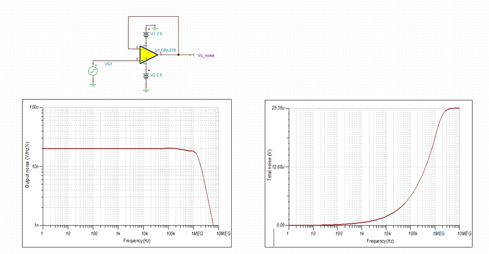
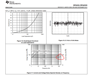
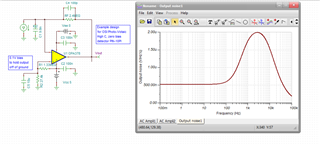
1. If we let the output simply self limit bandwidth wise, are we not going to run into a peaking voltage noise at some point? And - since the NG is very high out there, that might be an integrated noise question - I was thinking a post RC would be prudent, but the OPA378 does not show spot noise above 10kHz, some of the more recent choppers show it out further with the peaking intrinsic to the architecture. Without the peaking info in the spot noise, not sure where to put that post RC. 

2. Some of the chopper discussions talk about the effect of the chopper on input bias current? I am assuming that is not in the model, something that should be considered? - and here I am wondering if choppers should be banned from this app even with their great offset and drift? 

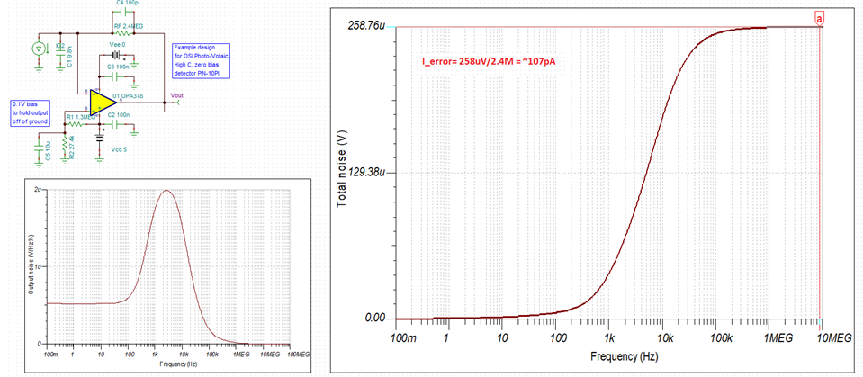
Here is an example from that OSI design requirement above, 

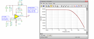
This shows pretty good output spot noise where the 2.4Mohm dominates until the noise gain gets really high, nothing too concerning at higher F - but that chopper noise is probably not in this macromodel. 

And the file, 

OPA378 Zt stage for OSI PhotoVoltaic.TSC

  • Michael,

    You may simulate the OPA378 input voltage noise spectral density beyond 10kHz shown in the datasheet.  Doing so shows 20nV/rt-Hz all the way to its 900kHz unity-gain bandwidth frequency - see below.

    However, I am not sure why would you use OPA378 with max Vos of +/-50uV and broadband noise of 20nV/rt-Hz instead of OPA392 with max Vos of +/-25uV and broadband noise of 4.4nV/rt-Hz.  Also, using it without additional filtering would result in at least 107pA error - see below.

    If you wish to minimize the current error by minimizing the offset and total noise, a better chopper op amp would be OPA387 with a broadband noise of 8.5nV/rt-Hz and max Vos of just +/-2uV. However, because of the dominance of thermal noise of 2.4Mohm resistor in TIA application shown below, one would still need to limit its bandwidth.

    Using filters at the output and across the feedback resistor could minimize the error down to 1pA - see below.

    The macro-model does not show the IB spikes themselves BUT it does include their effect on the total integrated IB magnitude. This is the reason why CMOS non-choppers' typical IB is in the range of 1pA while OPA387 and OPA378 IB's are 30pA and 150pA, respectively. Having said that, choppers' asymmetrical IB spike may be converted across unmatched input impedance into offset error and for this reason we recommend to match the input resistors whenever possible - just like we cancel IB related Vos error in bipolar input op amp without IB cancelation.  However, unlike other choppers, OPA387 and OPA333 have very well matched IB spikes and thus they are more immune to said IB commutation into Vos errors.   

    OPA387 Zt stage for OSI PhotoVoltaic - ML.TSC

  • Thanks Marek, 

    There are certainly better devices as you point out, but those come with much higher quiescent current of course. The OPA387 is 570uA vs the 125uA for the OPA378 I was starting with. The OPA392 is a great part, but in kind of a different class at 1.22mA. 

    Yes, you can simulate the voltage noise and it looks flat for the model - is that also true of the device? That plot stops at 10kHz and when I look at some choppers out there they do show increasing input noise. Is that a plot mistake? Maybe they had large R for that voltage noise measurement and picked up the current spike issue. 

    I think what you are saying at the end about the Ib matching on those spikes is you want to match source impedances - but would that not be at higher F meaning in this 2.4Mohm Zt example I would need 2.4Mohm without filtering on the V+ input? That might hurt the noise a bit. 

    For really low power low offset solutions the chopper looks interesting, Lacking data sheet or modeling info on the chopper noise effects at higher F, maybe the easier thing is to simple post filter a little above the desired signal bandwidth set by the feedbadk C. So here the design was trying to set a 660Hz feedback pole, so maybe a 2kHz post RC might remove these considerations? 

    Is there by chance a summary listing of chopper frequency by device number? I know generally, that might be hard to find but it seems to come up in e2e regularly. 

  • You don't see that increasing voltage noise so much in the TI parts, but here is one example - again stopping at 20kHz - starting up but not clear where it goes. 

    Out in the chopper frequency region, I vaguely recall some devices that shows all that noise in these kind of plots - maybe those were not TI parts? I think my point is I wonder if all those parts have that and maybe - 

    1. They are not shown in characterization

    2. They almost certainly are not in the customer models - but certainly in the design simulations

    Working with these gaps, perhaps a listing of chopper frequencies would allow some comfort setting that post RC frequency well below that. 

  • As I am sure you know, at the lower frequency the input noise spectral density is totally dominated by the input stage because noise of the other stages is attenuated by the gain of the first stage.  As one approaches the unity-gain bandwidth frequency, the input voltage noise spectral density tends to increase above the broadband level, due to the roll-off of the gain of the first stage (noise of the other stages becomes a factor) and then it gets attenuated by the bandwidth limitation. I believe the 20kHz upper frequency shown on the graphs simply comes from the limitation of the equipment used. 

    It's true that matching input impedances increases the noise by a factor of sq-rt(2) BUT it minimizes the offset error (caused by commutation of the unequal chopper IB spikes across mismatched input impedance), which in the first place is the main reason for using chopper amplifiers.

    As far as the chopping frequency goes, we typically specify it either in the application section or specification table of the datasheet - see below.