This thread has been locked.

If you have a related question, please click the "Ask a related question" button in the top right corner. The newly created question will be automatically linked to this question.

INA818: substitute INA126

Part Number: INA818
Other Parts Discussed in Thread: LM27762, , INA126, INA826, INA828, INA333, TPS65133, OPA365

Hello,

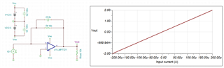
I need to amplify a signal with hundreds of mV DC + tenths of mV AC at tenths of kHz. The voltage signal will be read between a know precision resistor of 1 kΩ (initially, may change), in order to estimate the current going through an electrochemical cell.

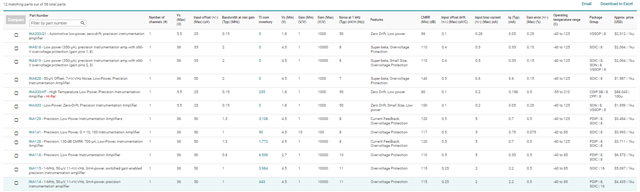
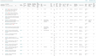
The team previously used INA126 in other projects, so that was the first component we considered using. But I would like to analyze the possibility to use INA818, as it has low noise, a wider range of selectable gain, can be supplied with dual 2.5 V (from a LM27762 for example). Recently I also saw in Mouser website that INA126 is "scheduled for obsolence".

Is it a viable change? Currently INA818 is out of stock, is there an estimated date for when I could buy it?

Thank you.

Kind regards,

Luiz Enger

  • Hi Luiz,

    Is it a viable change?

    Yes, you may replace INA818 for INA126; and INA818 is a direct p2p replacement. Of course, we have many other instrumentation options for the application. Enclosed is the analog engineers calculator to check the compatibility, which is mainly to compare Vcm vs. Vout, the differential Vmin and Vmax range for an instrumentation amplifier (IA) selection. 

    For noise data and other performance comparisons, we have to reference to their datasheet. If you selected INA818 IA, the application's differential input my be increase up to ±235mV range (instead of 175mV/-170mV range for INA126). 

    https://www.ti.com/tool/ANALOG-ENGINEER-CALC

    The following link is the selection of IA. Regarding the availability inquiry, I have to ask our marketing department. If you are able to confirm what you are looking for, I may be able to get the availability information for you. We have a very large IA selections, and I have filtered out the most of IAs in the link below. Based on what I see, INA333, INA826, INA828 and others may work for your replacement. 

    https://www.ti.com/amplifier-circuit/instrumentation/products.html#p480=1&p358max=5;36&p1181typ=0.001;2&p766max=25;50

    The voltage signal will be read between a know precision resistor of 1 kΩ (initially, may change), in order to estimate the current going through an electrochemical cell.

    You mentioned that the application is for measure current through electrochemical cell. In this application, the redox current may be small. Alternative method is using Transient Impedance Amplifier (TIA) to convert current to voltage.  Since you have the system working, I am not going to discuss other options. 

    If you have additional questions, please let me know. 

    Best,

    Raymond

  • Hello Raymond,

    Thank you very much for your reply! Fast and really informative. At the moment we haven't yet decided 100% on which IA model to use, so it is good to see other options. Availability is also an issue...

    Regarding the use of a TIA, we opted to use a topology in which the working electrode is connected direcly to ground, and not in a virtual ground configuration. Some bibliography research informed that this is a less noisy topology. It could be interesting to have further discussions.

    What I would appreciate the most at the moment would be to receive some support in the availability and purchase of Texas Instruments' components. In our BOM we have low noise amplifiers, IA, voltage regulators and so on. Beyond the substitutes for INA126, we are interested in acquiring OPA365 or similar, LM27762 or TPS65133 and LDOs to power up the opamps with dual 2.5 V, and possibly a rms-to-dc converter. Which models could you recommend?

    Thank you.

    Kind regards,

    Luiz

  • Hi Luiz,

    For three-electrochemical cell, TIA topology is often recommended to convert I-to-V to at Working Electrode (WE). The reasons are that the WE electrode's impedance may be high and the redox current range from CE to WE may have a wider range. It will be the best option to interface with WE electrode when the current and the impedance (high typically) are not known and have a wide range. This is especially true for potentiostat when an application is searching for redox spieces in an unknown electrolyte.   

    On other hand, if an application is working with a known electrolysis and you know your redox reaction and source/sink current, then the IA approach may be acceptable. Based on your previous inquiry, your WE is able to source/sink 100s mV across 1kΩ resistor, your application may be operating at a fixed peak redox potential vs. a reference. If this is the case, you may use the existing approach, if 1kΩ sensing resistor is not loading down the WE electrode. In other words, if an application is operating at fixed redox potential and there is enough current to source/sink at WE, then the IA's approach maybe acceptable. However, the electrochemical potential unit is designed for a very specific task and may not be flexible to adapt to other applications.   

    Over E2E forum, we do not handle supply issues on our products in general. I am an application engineer for Precision Op Amp Products. For LDOs and switching DC/DC or AC/DC converters, you may have to consult with TI's power support teams. Typically, we do not handle product availability information. However, we can ask our marketing team for the availability information, if you are interested in a specific product. 

    Below is a selection of precision op amp that may work for electrochemical interface in WE. I know that it may be difficult to find certain op amps under the current environment.  

    https://www.ti.com/amplifier-circuit/op-amps/precision/products.html#p480=1;1&p3247max=0.02;1&sort=p3247max;asc

    Below is an example of TIA I-to-V converter from -200uA to 200uA. If you provide me with design details, I can simulate one per your requirements. 

    LMP7721 uA TIA 03142022.TSC

    I am enclosing 3 application notes for your references. The top one is TIA for photodiode application. Although it is not the same as your application,  TIA design principle is the same. The remaining two are referenced to electrochemical sensor design. 

    https://www.ti.com/lit/ug/tidu535/tidu535.pdf?ts=1647218710685

    https://www.ti.com/lit/an/snoa529a/snoa529a.pdf?ts=1647240354907&ref_url=https%253A%252F%252Fwww.google.com%252F

    https://www.ti.com/lit/an/snoa514c/snoa514c.pdf

    BTW, many of our precision op amps under a given IC package have the same package pinout. Even you are unable to find the op amp you prefer at the moment, you may replace the part with a desired one when the part becomes available. We called that P2P replacement. 

    I provided a precision op amp link above. These op amps have high input input impedance (low Ibias current), which are suited for electrochemical interfaces. Some op amp has higher Vos than others, which you probably are looking for lower Vos types. Since I do not know your design requirements, I am unable to comment on the selection. If I have the design requirements, I can provide you with recommendations or suggestions. 

    Best,

    Raymond 

  • Hello Raymond,

    Do you have any experience regarding the difference in noise levels when the working electrode is connected to a virtual ground, such as in the case when a transimpedance amplifier is used, and when it is connected to system GND (considering the topology I mentioned, measuring the voltage drop in a resistor in series with the CE)?

  • Hi Luiz,

    Do you have any experience regarding the difference in noise levels when the working electrode is connected to a virtual ground...

    All classical 3-electrochemical configuration is design in this way where the WE is connected to virtual ground. The reasons are the current magnitude or electron flow at WE may be very low, from pA-nA to mA-Amp range, and the TIA node is required to have very high impedance to interface with the electrode (redox reaction occurred between WE and electrolyte interface).   

    What kind of noise levels are you observing at WE? The 3-electrodechemical cell is modeled such that redox current (opposite from electron flow) is sourced from CE to WE. For a given Vc is applied at WE, which is reference to RE electrode, CE will source or sink the required current to the WE, so that applied potential, Vc, at WE (vs. RE) is maintained.  

    You should not see significant level of noises at WE in a classical 3-electrodechemical setup, unless your application is operating at very low redox current (<nA range or close to the TIA's lowest detection level). Also, you need to aware that chemical engineer does not like to use switching power supply for 3-electrochemical configuration. If your application requires high levels of source/sink current for a redox reaction in the electrolyte, designers will typically convert or filter out switching power supply voltage to series linear regulator at CE electrode (keep in mind that CE electrode is really a current source regulator from its feedback). 

    From your previous current sensing scheme at WE electrode, the setup will only work for large redox current at WE. I recalled that the WE is connected to 1kΩ sensing resistor and connect it to ground. If your application is doing a fixed potential electrolysis (reduction or oxidation occurred at WE electrode at a peak redox potential), where high level of redox current is able to source/sink from CE electrode, then such setup may be acceptable.  

    If your 3-electrochemical configuration has to work like a standard potentialstat, where WE's potential has to scan across a potential range, say from -Va to +Vb at scanning rate of 1mV-to-100mV/sec vs. REF, then you will see noise issues from the current measurement. When no redox spieces are occurred at WE electrode, the current is very small (in pA to nA range depending on the surface area of WE electrode), and the WE is unable to source or sink current properly because of 1kΩ load at the output of the WE electrode. In other words, WE is being loaded down by the sensing resistor, and will disturb the "redox" reactions occurred at the chemical electrolyte interface between WE and electrolyte.

    I hope that this helps. Please let me know if you have additional questions. 

    Best,

    Raymond 

  • Hi there Raymond,

    What I have is the working electrode directly to system's GND, and a series resistor, called Rm, between the output of U1 and the tip of CE. Then I use an instrumentation amplifier to read the voltage drop across Rm.

    We did not perform experimental noise analysis between different topologies. We opted for this one as literature indicated as the less-noisy option, and we do get readings. We also use a voltage follower between RE and the inverting input of U1, to have a low output impedance node and check the signal with a probe.

  • Hi Luiz,

    Do you have the literature reference that you can reference it to over the internet?

    I have used many high end of potentiostats over the years and I recalled that it is all done via TIA or I-to-V methods. I have not performed noise analysis between the two topologies, but I am interested to know the reasons behind the claim. 

    As I indicated that CE to WE electrodes are modeled as electrolyte impedance in series with a current source. In theory, the ideal current source should have infinity in impedance. However, CE to WE path has finite impedance. When a Rsense resistor is inserted after WE to ground, I am wondering if there is a voltage divider action measured the current across the sensing resistor. Under a very high impedance conditions, Rsense value may be neglected in influencing the redox current measured at WE. However, I do not believe that this is the case under all redox conditions at WE. 

    My guess is that under certain scenario, the classic TIA approach at WE has advantages, while Rsense current measurement with IA under certain conditions may contribute less noise. So I am interested to read the article and want to know what assumption or claims were made by the author. Anyway, please let me know. 

    Best,

    Raymond

  • Hey there Raymond,

    I'll be sure to share with you the articles. At the moment I'm really busy doing other activities but I do want to have this very interesting discussion with you! We could perform further investigations on the subject.

    Just a heads-up: the Rsense resistor is inserted BEFORE CE, from the output of the control amplifier to the "input" of CE. Then WE is connected directly to ground WITHOUT any added resistor.

    Thanks again for you time.

    Kind regards,

    Luiz Guilherme Enger

  • Hi Luiz,

    Ok, we can do some simulation and compare the two topologies in the application. Please let me know. 

    Best,

    Raymond