This thread has been locked.

If you have a related question, please click the "Ask a related question" button in the top right corner. The newly created question will be automatically linked to this question.

OPA333: Failure mode resistance on amplifier input.

Part Number: OPA333

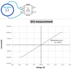
We have a product based on OPA333AIDBVT. After working a certain time, the + input pin (pin 3) showed a failure mode where its impedance to GND is 270 ohms instead of high impedance. A deep analysis of the board showed that the problem is on the amplifier, not the PCB. We don't know the use conditions when the problem appeared.

We want to know if you can provide some informations about which conditions can generate such a failure.

  • Hi Gregory,

    We want to know if you can provide some informations about which conditions can generate such a failure.

    Could you share the schematic with us? Could you describe the type of input signals present at OPA333's analog front end or the designed application? 

    One of likely scenario is that the design may not limit the input current at the analog front end of OPA333. When the input voltage exceeds the power supply rail momentarily, ESD protecting diodes may be conducting momentarily and resulted excessive conducting current going through ESD diodes. The input current has to be limited <10mA.  

    Best,

    Raymond

  • The front end is an IR sensor with output impedance of 75kohms. I cannot share this document as it is confidential. In standard conditions, I see no possibility to have an overvoltage. But you are right ESD is one possible way. My question is more: can an ESD generate this failure mode (i.e. 270 ohms behavior)? Also, can an over temperature also generate this failure mode?

  • Hi Gregory,

    Without a schematic, I can only speculate possible failures. 

    ESD breakdown may cause the PN junction to be failed short (or near short), which is a possibility. However, the ESD breakdown interface may fail open as well, though this scenario is rare in general. 

    With IR sensor (PbS, PbSe or other resistive type of IR detectors) at the input op amp, the input front end is likely configured as voltage divider. Is there a path that op amp's input voltage exceeds the supply rails by ±0.3Vdc? Say the during sensor's power up or power down in detecting sequences. 


    If IR sensor is NIR or voltaic type, the above scenario may be possible. 

    Also, can an over temperature also generate this failure mode?

    The over temperature on its own should not generate this type of failure. With PN junction, ESD may conduct sooner due to -2mV/C shift, but OPA333's analog front should implement current limiting resistor to protect the input. 

    How many failed parts have you observed so far? Without much failure details and schematic, I can only speculate. If OPA333 does not have the recommended current limiting resistor, I will place one and record the failure units or scenario from now on. OPA333 is a very mature and rugged products, and I do not foresee that the type of failures, unless operating parameters are exceeding the OPA333's datasheet and/or performance specification, like EOS or other unknown sensing events.  

    If you have additional questions, please let me know. 

    Best,

    raymond 

  • Adding to Raymond's comment, any ESD event above the ratings shown below could damage the input stage of OPA333.

    Having said that, you may NOT measure input impedance with power supplies floating. The true op amp input impedance must be measured under normal biasing conditions with input and output voltage within the op amps linear range.