This thread has been locked.

If you have a related question, please click the "Ask a related question" button in the top right corner. The newly created question will be automatically linked to this question.

OPA2320: Got phasedelay, when outputvoltage exceeds operating range

Part Number: OPA2320
Other Parts Discussed in Thread: TINA-TI

Hello,

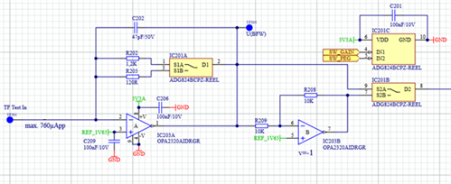
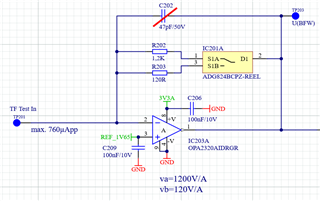
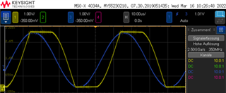
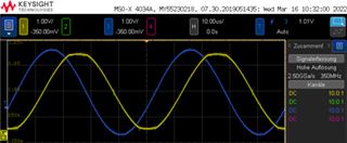
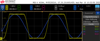
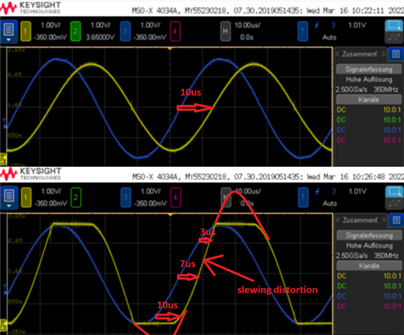
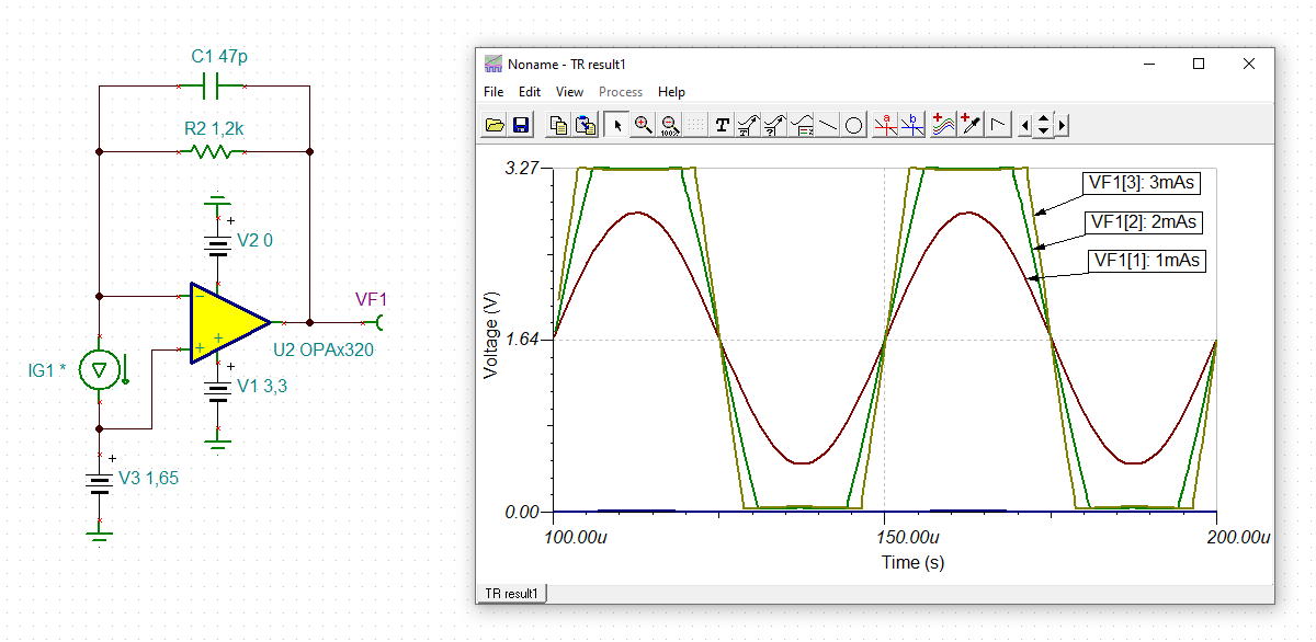
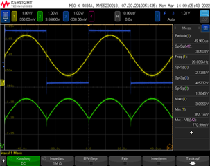
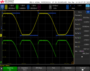
I use the OPA2320 as transimpedance amplifier. If the output voltage exceeds the operating range, the outputsignal gets a phase delay.

In chapter 7.3.4 of the datasheet (Fig. 34) is shown, that the amplifier has no phase reversal.

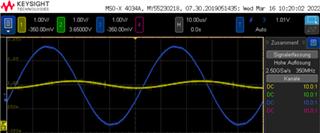
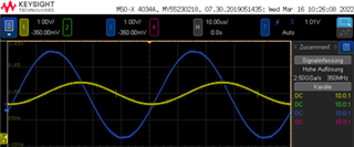
I attach some pictures to show my problem. The inputsignal is a sine, synchron to the blue signal; the outputsignal is the yellow one. If the amplitude rises boyond the operating range the phase of the (yellow) output is shifted. (The green signal is the output of a Phase Sensitive Detector.)

Can anyone give some advise to avoid this behavoir or can recommend some (pin-)compatible amplifier?

Is this a known issue?

Thanks, Jan

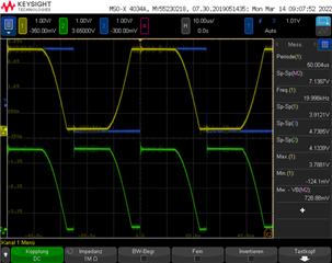
Edit: I would expect an rectange or trapezial signal at the output.

The supply voltage of the OPV is 3.3V single supply

  • Hi Jan,

    such "phase shifts" can easily be seen when relevant capacitances are in the feedback loop. Think of the detector capacitance, e.g. By the way, what you see is no phase reversal.

    Can you show a schematic?

    Kai

  • Allowing the output to slam against its rail results in the non-linear operation of the op amp's output where upper or lower output transistor becomes a resistor (Ron).  As the output is suddenly pulled away from its rail, the output stage must first re-bias itself resulting in a time delay - this condition is called overload recovery time and occurs in all op amps.

  • Hi,

    thanks for your answers! I just posted the schematic in my first post.

    : There are no "big" capacities. I removed the 47pF (C202) for tests, but nothing changes.

    : The overload recovery Time of the OPA2320 is 100ns. The timedelay seems to be in the range of ~10µs.

  • Hi Jan,

    what exactly is connected to pin 2 of OPA2320, the input of your circuit?

    Kai

  • Its an amplitude-modulated current signal.

    I made some more measurements which show the direct input of the connected measuring system and the outputsignals with the small and the high gain (R202 / R203 connected).

    This is the actual schematic with the removed capacitor:

    The output of the schematic supplyes an other amplfier.

    My measuring results (yellow: TP203, blue: Source signal of measuring system). As you can see the phase offset of the measurung system is constant, because with the small amlified signals have a constat phase delay.

    Small Gain (120V/A) High Gain (1200V/A)

    Note the zero crossings (1,65V / grey line) of the yellow signals. These move about 7µs from the first to the third row, with the high gain.

    Jan

  • Hi Jan,

    it could have to do with the circuit driving the OPA2320. What physical circuit is connected to pin 2 of OPA2320? Is a cable involved?

    Kai

  • Jan,

    I believe what you see is a simple time delay related to a phase shift that has little to do with the output exceeding its linear voltage range - see below.

    As you may see below, 10us delay in the top undistorted waveform is caused by approximately 90 degrees phase shift between the input and output signals: t = (90/360)*T, while the lower distorted waveform shows changing time delay due to additional distortion caused by the output slewing as it comes off the rail.

    In other words, if you did not exceed the output linear range, you would expect the same 10us time delay in the lower waveform as you see in the upper waveform.  And the fact that the lower output waveform is distorted does not change the reasons behind the output signal time delay - it is still related to the output signal phase shift of around 90 degrees but it changes because the output signal is also forced to slew after falling behind due to the output non-linear operation.

  • : the circuit driving the OPA3020 is some kind of inductive measuring system. There is no cable involved, but some centimeter flex-pcb.

    I think could be right. The 10µs delay is clear and no problem. The smaller delay (7µs) seems to come from the operation in the non linear range. Do you have any idea to keep the contstant delay of 10µs in the linear range? At least in the zero crossing?

    Has this to to with some kind of recovery time, which the amplifier needs, when it comes out of the non linear range?

    Thank you so far

  • Hi Jan,

    yes, but the TINA-TI simulation shows something totally different, when assuming a sine current of 1mApeak, 2mApeak and 3mApeak:

    jan_opa2320.TSC

    I think it has something to do with your current source. Your current source doesn't seem to be a true current source, but some complex impedances seem heavily to work here. I think it has to do with your inductive measurement system. When the input signal becomes too high, the OPAmp leaves its normal operation point and does no longer work linearily. Becasue of this the -input is no longer at virtual ground. Then the "current source" with its complex impedances is dancing Polka with the OPAmp Relaxed

    Kai

  • Hi Kai,

    yes, the simulation shows, what I would expect. I think the measuring system has some complex impedance, but the inductive part should be the dominating.

    The measuring system is used in several of our systems and so far without any complications. For a new application I tried to use a new OpAmp and got those problems. In earlier projects we used some other OpAmps.