Other Parts Discussed in Thread: INA219, INA190
Per the simplified schematic in the datasheet, how does this work to supply the device V+ with 3.3 and a common mode input voltage of 24V? Its a little unclear in the datasheet how this is accomplished, as the common mode at the op amp input would be much higher than the supply. (According to the simplified schematic)
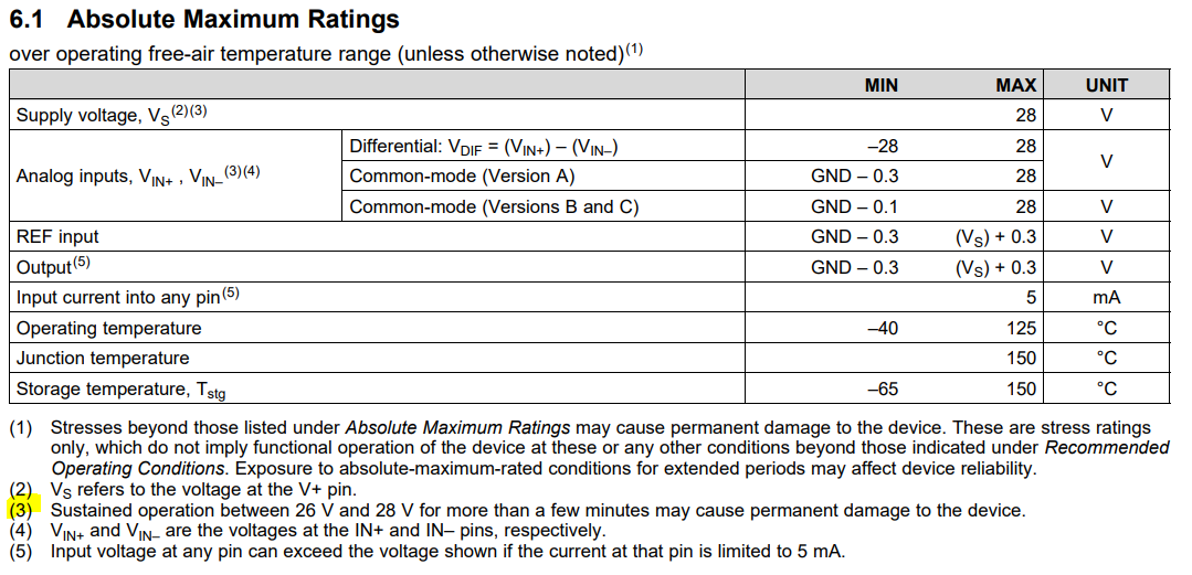
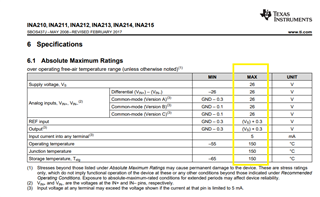
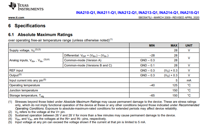
Typically there is some difference between rating and Absolute Maximum values, in this case 26V. In order to follow transient voltage suggestions, this isn't so easy, as for example a 24V tvs doesn't have a very sharp knee, with the VBR starting well over 26V. Any ideas on how this could be handled, or if it is necessary?
I'm using these with a 10mOhm sense resistor for a 2A range. They will be upstream from a soft start PMOS switch.