This thread has been locked.

If you have a related question, please click the "Ask a related question" button in the top right corner. The newly created question will be automatically linked to this question.

INA199: Current Measurement Using INA199 and ADS8684

Part Number: INA199
Other Parts Discussed in Thread: ADS8684, TIDA-00753, , INA214

Hello,

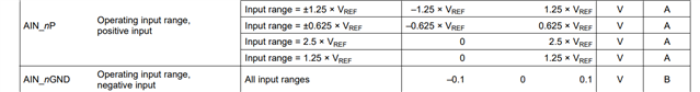
I am designing a new current measurement device. But I am measuring 1.251V on ADS8684's both AIN_N and AIN_P pins.

Here are my design notes:

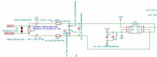
- I am using a current transformer. Here is the datasheet: https://cdn.ozdisan.com/ETicaret_Dosya/480697_631942.pdf

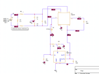
- My current measurement analog circuit is based on TIDA-00753. Here is the schematic:

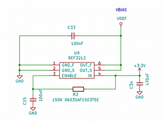
- This is my reference voltage circuit:

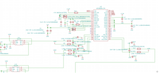
- INA199's output and reference voltage is tied to ADS8684 pins:

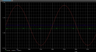
- Before designing, I made some simulations using PSpice for TI. I don't have INA199 in my PSpice library, so, I used INA214 in my simulations. The current transformer range is 0-10A and it has 1:1500 ratio. At 10A, I will get 0.0066V.  I used 0.0066V sinusoidal signal to my simulations.

- My design measures 3-phase currents. The microcontroller's console output prints ai1, ai2 and ai3 values for first, second and third phase analog values.

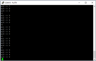
As you see the console output above, there is no value while 0.7A current flows inside the current transformer. I am measuring 1.251V both on R4 and R5.

Could you please make comment why I am not getting as my simulations?

Best regards,

Onur

  • Hi Onur,

    the problem is that you haven't provided a path for the input bias currents of INA199 to signal ground. See figure 20 of datasheet.

    You could connect the left side of R37 to V+ (3.3V).

    By the way, as the current transformer provides galvanic isolation and removes any nasty common mode voltages, you would not need to use a current sense amplifier. A simple OPAmp can do.

    Kai

  • Hello Onur,

    I agree with Kai that there is no biasing Common mode voltage at the inputs of the INA199.  This will be set by parasitic on your board normally if left floating along with the input bias currents required by the INA199 as seen in figure 8 of the datasheet.

  • Hello,

    Are you sure about that? Why doesn't TIDA-00753 have that connection?

    By the way, I connected 3.3V supply between FB3 and R37. And same situation continues. There is no analog value on ADS8684.

    Onur

  • Hello,

    I guess the reference is biasing the inputs. Have you removed R4 and verified the INA199 output with a scope?  I would assume that the output of the INA199 is correct but you are overdriving the input to the ADC.  The ADC is not fully differential and the Ain_nGND must be close to GND.