This thread has been locked.

If you have a related question, please click the "Ask a related question" button in the top right corner. The newly created question will be automatically linked to this question.

OPA564-Q1: Is it OK to choose OPA564 as the driver of this DFB Laser?

Part Number: OPA564-Q1
Other Parts Discussed in Thread: OPA564,

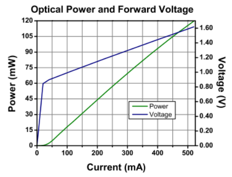
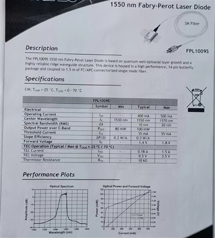
I want to find a driver for this DFB laiser, whose parameters are listed as below.
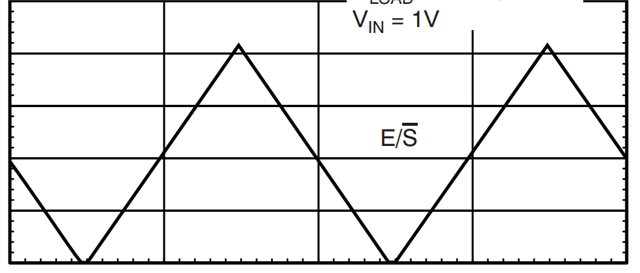
The triangular wave is used as the input to control the Laser, whose frequency is almost 100KHz.

You can have a look at the trianglular wave, listed as below.
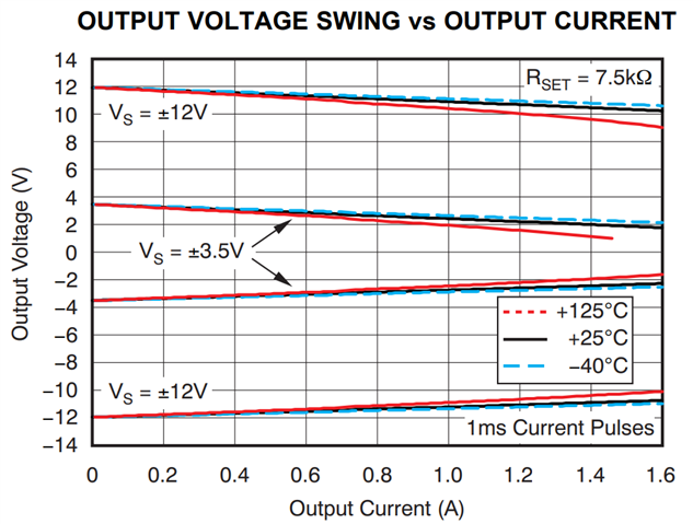
According to the SPEC of OPA564,  is it possible for this laser working with the current being 500mA and the voltage being 1.8V?
  • Hello,

    The output current required by the laser diode is certainly within the capability of the OPA564-Q1, and its BW and slew rate should support the 100 kHz triangle wave. Since the triangle wave is only about 4 Vpp, I suggest using a minimum supply (+/-V) to minimize power dissipation. Do you have an idea what supply voltage you might use?

    Laser diodes must have their maximum current limited so that they are not damaged by overcurrent. The OPA564-Q1 has resistor programmable, adjustable current limit so that can be used to advantage.

    Regards, Thomas

    Precision Amplifiers Applications Engineering

  • I want to use a single power supply and I2V will be used.

    In the end, would  you please suggest me a reference design on being a laser driver?

    Thanks a lot.

  • Hi ,

    I want to use a single power supply and I2V will be used.

    I need more information from you. What I2V are you referring to?

    1. What is amplitude of sawtooth wave at 100kHz? Thomas mentioned 4Vpp and your diagram is not clear with Vin = 1V? Please specify. 

    2. Based on the laser diode forward voltage vs. current, the laser diode's forward voltage should be controlled from 1.0V to 1.8V, and the diode current is regulated from 80mA to 500mA.

    3. Does the laser diode regulate the driving current first, and cap the diode voltage? Or does the diode regulate the forward diode voltage and cap the driving current?

    4. The sample circuit on the right is a V-to-I controller, where input voltage Vg controls the current going through the laser_diode.  If the input Vg is sawtooth signal, the driving current though the diode is going to be a sawtooth as well. 

    Best,

    Raymond

  • Firstly, thank you for your response.

    1.I need more information from you. What I2V are you referring to?

    A: V+ will be supplied with 12V and V- will ben connected to GND.

    2. What is amplitude of sawtooth wave at 100kHz? Thomas mentioned 4Vpp and your diagram is not clear with Vin = 1V? Please specify.

    A:The amplitude of the sawtooth wave is 1.8V.Therefore, Vin will be changed from 0V to 1.8V.

    3. Does the laser diode regulate the driving current first, and cap the diode voltage? Or does the diode regulate the forward diode voltage and cap the driving current?

    A: I think the current will be changed according to the change of the voltage.

    Thanks a lot.

  • Hi User5811580, 

    If I understood the FPL10095's requirement, the main control is the laser diode is the current (may be the average current, the feedback signal to maintain the diode current is the optical power, which is shown in green line. So the current may be the peak current of 100kHz sawtooth of the applied peak voltage at input. The forward diode voltage is not the secondary control as long as it does not exceed 1.8Vpk. The circuit's feedback is the optical power of the laser diode, which is measured at the output laser diode or emitter at nominal of 1550nm. 

    Question: How do I get the optical power feedback for the laser current control? I do not believe that I have all the information to provide you with a reference design.  

    If my understanding is incorrect, please provide me some understanding how the Op Amp control loop is constructed. 

    Best,

    Raymond